Free-Body Diagrams: Solved Problems
In this article, you can learn more about free-body diagrams using the problems-solutions approach.
Free-Body Diagrams: Introduction
In solving any dynamic problem, it is useful to identify all forces acting on an object and then illustrate them in a single diagram, called a free-body diagram.
In these diagrams, the object is depicted as a particle in a suitable coordinate system.
Free-Body Diagrams: Problems
The tactics for drawing any free-body diagram are as follows:
(a) Identify all forces acting on the object.
(b) Draw a suitable coordinate system. ''Suitable'' means that, for example, for an object along an inclined plane, a tilted coordinate system with the x-axis parallel to the slope is the best option.
(c) Draw each force on the diagram according to its magnitude.
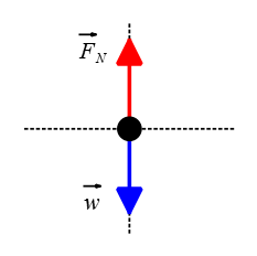
Problem (1): A block of mass 10 kg is placed on a rough horizontal surface. Draw the free-body diagram for the block when it is at rest.
Solution: First, let's identify the forces acting on the block.
1. Weight ($\vec{w}$): The weight of the block acts vertically downward and is equal to the mass of the block multiplied by the acceleration due to gravity ($\rm 9.8\, m/s^2$).
2. Normal force ($\vec{N}$): The normal force acts perpendicular to the surface and counteracts the weight of the block. Since the block is at rest on a horizontal surface, the normal force will be equal in magnitude and opposite in direction to the weight of the block.
3. Frictional force ($F_f$): The frictional force acts parallel to the surface and opposes any tendency of motion between two surfaces in contact. The block is at rest on level ground, so there is no frictional force.
Note that the block is at rest on the surface, so the net force $\vec{F}_{net}$ acting on the block must be zero. As a result, all forces identified above must be drawn in equal magnitude.
Now that we have identified all forces acting on the block and their magnitudes qualitatively, we can draw a free-body diagram:
Note: It's important to remember that free-body diagrams are simplified representations of the forces acting on an object. They do not include other factors such as air resistance or internal forces within the object.
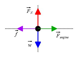
Problem (2): A car of mass 1000 kg is moving with a constant velocity on a horizontal road. Draw the free-body diagram for the car.
Solution: To draw the free-body diagram for the car, we need to consider all the forces acting on it. In this case, since the car is moving with a constant velocity on a horizontal road, there are three main forces to consider:
1. Weight (W): This force is always acting vertically downwards. The weight can be represented by an arrow pointing downward from the center of the car.
2. Normal force ($N$): This force acts perpendicular to the surface of contact between the car and the road. Since the car is not accelerating vertically, the normal force must be equal in magnitude and opposite in direction to the weight. Therefore, it can be represented by an arrow pointing upward from the center of the car.
3. Frictional force ($f$): This force acts parallel to the surface of contact between the car and the road and opposes its motion. Since the car is moving at a constant velocity, this frictional force must be equal in magnitude and opposite in direction to any external forces that may try to slow down or speed up the car. The frictional force can be represented by an arrow pointing in a direction opposite to that of motion.
4. External force: in this case, the force produced by the engine is the one responsible for pushing the car forward. Here, we have denoted it by $F_{engine}$.
Overall, your free-body diagram for a car moving with constant velocity on a horizontal road should look like this:
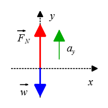
Problem (3): A person is standing on a weighing scale inside an elevator that is accelerating upwards at 2 m/s². Draw the free-body diagram for the person.
Solution: To draw the free-body diagram, we need to consider all the external forces acting on the person.
1. Weight ($\vec{w}=m\vec{g}$): The weight of the person acts vertically downward.
2. Normal force ($\vec{F}_N$): The normal force acts perpendicular to the surface of contact between the person and the weighing scale. It counteracts the weight of the person and prevents them from sinking into or falling through the scale. In this case, since there is an upward acceleration, the normal force will be greater (longer arrow) than just balancing out gravity (smaller arrow).
The elevator is accelerating upward, so according to Newton's second law of motion, there must be an upward net force. Hence, the magnitude of $\vec{F}_N$ will be greater than $\vec{w}$ due to upward acceleration, resulting in a net upward force on the person.
The free body diagram for a person standing on a weighing scale inside an elevator accelerating upwards would look like this:
Keep Going: If you enjoyed this example, here are more elevator motion problems with solutions.
Problem (4): In a rotating vertical cylinder (Rotor rider), a person feels as though they are being pressed against the wall with their back. Draw a free-body diagram for this case.
Solution: The forces acting on the person include the downward weight force ($\vec{w}$), the normal force ($\vec{F}_N$) directed away from the wall toward the center rotation, and the force of friction parallel to the wall and directed upward (opposing the downward weight force).
To create a clear representation of these forces, we can assemble them into a coordinate system, as shown in the figure below. This diagram is known as a free-body diagram for a rotating vertical wall.
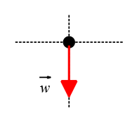
Problem (5): A ball of mass 0.5 kg is thrown vertically upward with an initial velocity of 10 m/s. Draw the free-body diagram for the ball at its highest point.
Solution: At the highest point of its trajectory, the ball is momentarily at rest. Therefore, the only force acting on it is the force of gravity pulling it downward.
In all free-falling problems in which objects are tossed straight up into the air (with negligible air resistance), the only external force that is exerted on the object is the weight force, $\vec{w}$, downward. Therefore, the free-body diagram for this case is depicted below.
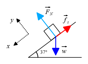
Problem (6): A box of mass 20 kg is standing on an inclined plane with an angle of inclination θ = 37°. Draw the free-body diagram for the box.
Solution: To solve this problem, it is better to adopt a tilted coordinate system with the $x$-axis parallel to the inclined plane, whereas the positive $y$-axis is perpendicular to the incline. The free-body diagram would include the following forces:
1. Weight ($\vec{w}$): This force acts vertically downward, not along our chosen negative $y$-axis.
2. Normal force ($\vec{F}_N$): This force acts perpendicular to the surface of the inclined plane as shown in the figure below.
3. Friction force ($\vec{f}$): In this scenario, the static friction between the slope and the box prevents it from sliding down. If this type of friction did not exist, the box would slide down the slope. Therefore, static friction must be directed up the slope to counteract the component of the weight force down the slope, resulting in the box remaining at rest.
Problem (7): A rocket is launched vertically upwards from the Earth's surface with an acceleration of 20 m/s² due to its engines. Draw the free-body diagram for the rocket at its highest point.
Solution: At the highest point of its trajectory, the rocket momentarily comes to rest before it starts to fall back down. Therefore, the only force acting on it is the Earth's gravity, which pulls it downward towards the center of the Earth.
The free-body diagram for a rocket at the highest point of its trajectory is the same free-body diagram as an object thrown vertically upward.
Note: If we were asked to determine the forces acting on the satellite at any point except at the highest point of its trajectory, we would also need to include the thrust force that propels (pushes) the satellite forward.
Additionally, we must consider the air drag force, which opposes the direction of motion and arises from interactions between the satellite and air molecules. Consequently, the free-body diagram would include these additional forces.
Problem (8): A pendulum bob of mass 2 kg is swinging back and forth in simple harmonic motion with no air resistance present. Draw the free-body diagram for the bob at its maximum displacement.
Solution: In a back-and-forth motion, like that of a pendulum bob, the maximum displacement of the object occurs when it is instantaneously at rest. (Recall that in harmonic motion problems, this distance is referred to as the amplitude of the oscillations.)
First, let's identify all the forces acting on the bob as it moves back and forth.
The tension force $\vec{T}$ of the string attached to the bob pulls it toward the center of the semi-circular path along the string. The other force acting on it is the weight force $\vec{w}$, which acts vertically downward.
Since there is no air resistance present, there are no other forces acting on the bob.
Therefore, we can depict the free-body diagram for this case as shown in the figure below.
Problem (9): A satellite is orbiting around Earth in a circular path at a constant speed. Draw the free-body diagram for the satellite.
Solution: For a satellite moving in a circular orbit, the gravitational force $F_g$ is the only force acting on it.
The satellite is attracted to the center of the Earth due to gravity. This force acts towards the center of the circular path and is responsible for keeping the satellite in orbit. This force is called the gravitational force.
Therefore, we can draw a free-body diagram for the satellite as follows:
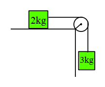
Problem (10): Two blocks, one of mass 5 kg and another of mass 10 kg, are connected by a string passing over a pulley, as shown in the figure below. Draw separate free-body diagrams for each block.
Solution: In cases where two blocks or bodies are connected by a string (or rope), it is better to cut the rope at a certain point and then indicate the direction of the tension in each rope with two incoming arrows.
The forces acting on the $5\,\rm kg$ block are as follows:
The downward weight force $\vec{w}$, and the tension force of the rope that keeps the block hanging directed upward.
Similarly, the forces acting on the $10\,\rm kg$ block are also the downward weight force, the tension in the rope, directed rightward, and the normal force $\vec{F}_N$, directed perpendicular to the surface.
Since the two objects are connected by a string, the tension force for each block is the same.
Therefore, the free-body diagram for this system is as follows:
Problem (11): A cyclist is riding his bike up a hill inclined at an angle θ = 15° to the horizontal, experiencing a constant force of gravity and a frictional force. Draw the free-body diagram for the cyclist.
Solution: Similar to all free-body diagram problems, first identify all forces acting on the object. The object is moving along an inclined plane, so it is better to consider a tilted coordinate system with its $x$-axis parallel to the slope, as shown in the figure.
The weight force $\vec{w}$ pulls the object vertically downward, not along our chosen negative $y$-axis.
The slope's floor also exerts a force perpendicular to the surface, called the normal force $\vec{F}_N$, directed to our chosen tilted positive $y$-axis.
As the cyclist is riding uphill, there is a frictional force that opposes the motion and acts downward along the negative $x$-axis, directed down the slope.
Assuming negligible air resistance, these three external forces are all the forces acting on the cyclist moving over an inclined plane.
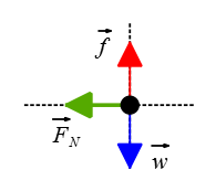
Problem (12): A person is pushing a crate weighing 50 kg across a rough surface with a constant velocity. Draw the free-body diagram for the crate.
Solution: The free-body diagram for the crate would include the following forces:
1. Downward weight force, $\vec{w}$.
2. The normal force exerted by the surface on the crate, $\vec{F}_N$.
3. The force of friction opposing the motion, $\vec{f}$.
4. The external force that the person is exerting on the crate, $\vec{F}$.
All these forces are assembled into a free-body diagram as shown in the figure below:
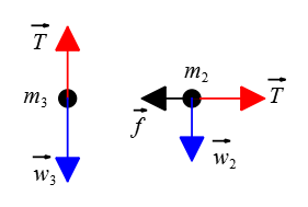
Problem (13): A block of mass 2 kg is placed on a rough surface with a coefficient of friction μ = 0.3 and connected to another block of mass 3 kg by a string passing over a pulley as shown in Figure Y (provide figure). Draw separate free-body diagrams for each block.
Solution: To solve this question, we need to draw separate free-body diagrams for each block and then analyze the forces acting on them.
First, let's draw the free body diagram for the $2\,\rm kg$ block. Since it is placed on a rough surface, there are two main forces acting on it:
1. Weight ($\vec{w}$): This is the force due to gravity and can be calculated using the formula $W=mg$.
2. Normal force ($\vec{F}_N$): This is the force exerted by the surface on the block perpendicular to it. It acts in the upward direction and has the same magnitude as weight but in the opposite direction.
Additionally, there is a frictional force acting on block $m_2=2\,\rm kg$ due to its contact with the rough surface:
3. Frictional force (f): This force opposes the motion, and its magnitude can be calculated using $f=\mu N$, where $\mu$ is the coefficient of friction (0.3) and $N$ is the normal force.
4. Tension force ($\vec{T}$)
Now let's draw the free body diagram for the $\rm 3 kg$ block connected by a string passing over a pulley. The downward weight force and upward tension force are the forces acting on this block.
Since both blocks are connected by a string passing over a pulley, they experience equal magnitudes of tension force ($T$).
These free-body diagrams help us understand the forces acting on each block and will be useful in solving further questions related to this system.
Problem (14): A ball weighing 0.2 kg is thrown horizontally with an initial velocity of 15 m/s from the top of a building. Draw the free-body diagram for the ball just after it leaves the thrower's hand.
Solution: The only external force that acts on the ball just after it leaves the thrower's hand is the ball's weight force.
Weight ($\vec{w}$): This force acts vertically downwards and is equal to the mass of the ball (0.2 kg) multiplied by the acceleration due to gravity ($\rm 9.8 m/s^2$).
Since the ball is not in contact with any surface, there is no normal force acting on it. On the other hand, assuming air resistance is negligible, this force can also be ignored.
Therefore, the free body diagram would show only one force acting on the ball, which is its weight (mg) pointing downwards.
Keep in mind that in all projectile motion problems, the weight force is the only force acting on the body if air resistance is negligible.
Problem (15): A person is standing on an elevator that is moving upward at a constant velocity. Draw the free-body diagram for the person.
Solution: The elevator is moving upward at a constant velocity, which means that its acceleration is zero. As a result, the net force (or the resultant of forces) on the person is also zero, $F_{net}=0$. As always, the weight force acts vertically downward, representing the gravitational pull on the person's mass.
There is contact between the person's feet and the elevator's floor, so a normal force $\vec{F}_N$ must also be present to support the person's weight.
Since the elevator is moving at a constant velocity, both of these forces must be depicted in a free-body diagram with equal magnitudes but opposite directions.
Author: Dr. Ali Nemati
Date Published: July 28, 2023
© 2015 All rights reserved. by Physexams.com
AP® is a trademark registered by the College Board, which is not affiliated with, and does not endorse, this website.