Torque Practice Problems with Solutions: AP Physics 1
When you want to rotate a body about an axis or a point, the direction and location of the applied force are also important, in addition to its magnitude.
Let's assume you want to open a door. Is it easier to open the door by applying a force to the doorknob or applying the same force magnitude to a point closer to the hinge?
It is an everyday observation that opening the door by exerting force at a point far away from the hinge is easier.
The distance perpendicular from the line of action of the force to the axis of rotation is called the lever arm or moment arm and is designated by $r_{\bot}$ as shown in the figure below.
In this manner, the torque $\tau$ is defined as the simple product of the lever arm $r_{\bot}$ and the force magnitude $F$, \[\tau=r_{\bot}F\] The direction of the torque is found using the right-hand rule.
In the following, we are going to practice some simple problems about torque to deepen our understanding of these concepts.
Torque Practice Problems
Problem (1): In each of the following diagrams, calculate the torque (magnitude and direction) about point $O$ due to the force $\vec{F}$ of magnitude $10\,\rm N$ applied to a $4-\rm m$ rod. Both the force $\vec{F}$ and the rode lie in the plane of the page.
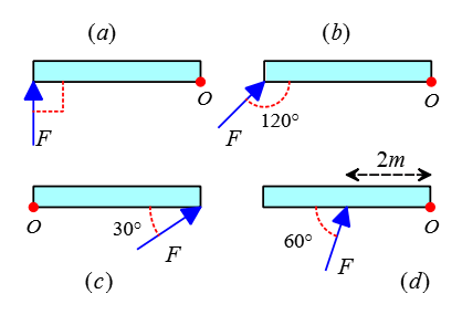
Solution: As said in the introduction above, the lever arm times the applied force gives us the torque about a point or an axis of rotation. First, we must identify the line of action and then the lever arm $r_{\bot}$.
We reach the line of action of the force by extending the applied force along a straight line in both directions. Now draw a perpendicular line from the point of rotation to that line so that it intersects it at a point. This distance is called the lever arm.
For simplicity in the calculation, the lever arm is always formulated as $r_{\bot}=L\sin\theta$, where $L$ is the distance from the point of application of the force to the axis of rotation and $\theta$ is the acute angle between the force $\vec{F}$ and the line connecting $F$ to the $O$.
We repeat this procedure for each case separately.
(a) In this figure, the line of action of the force is already perpendicular to the axis of rotation. Thus, the lever arm is the full distance between the point of application of the force $F$ and the point $O$, i.e., $r_{\bot}=4\,\rm m$. Therefore, the torque magnitude $\tau$ about point $O$ is calculated as \begin{align*} \tau&=r_{\bot}F \\&=(4)(10) \\&=40\,\rm m.N \end{align*}
(b) To find the torque of this configuration, extend the force $F$ and draw a line perpendicular to it so that it passes through the axis of rotation.
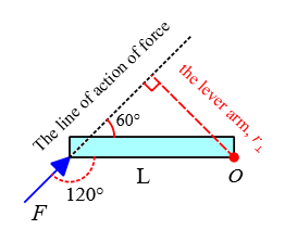
In this case, instead of using geometry to find the lever arm, we use the following formula to understand its application. \begin{align*} r_{\bot}&=L\sin\theta \\ &=4\sin 60^\circ \\ &=2\sqrt{3} \quad \rm m \end{align*} Now, substituting this value into the torque formula, yields \begin{align*} \tau&=r_{\bot}F \\ &=(2\sqrt{3})(10) \\ &=20\sqrt{3}\quad\rm m.N \end{align*}
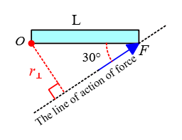
(c) Again, identify the lever arm and compute the magnitude of the torque associated with this force about point $O$. \begin{align*} \tau&=r_{\bot}F \\ &=(L\sin\theta) F \\ &=(4\sin 30^\circ)(10) \\&=20\quad\rm m.N \end{align*}
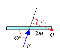
(d) In this configuration, the angle between the force line and the direction of the rod is $\theta=60^\circ$. Hence, the magnitude of the torque about the axis of rotation $O$ is found as \begin{align*} \tau&=(L\sin\theta)F \\ &=(4\sin 60^\circ)(10) \\&=20\sqrt{3}\quad\rm m.N \end{align*}
Isn’t this content as valuable as a $10 private class? Please support me here. I worked hard to prepare this article.
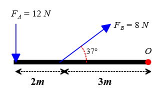
Problem (2): Two forces ($F_A=12\,\rm N$ and $F_B=8\,\rm N$) are applied to a $5-\rm m$ stick as in the figure below. The rod and the forces are on the plane of the page. Calculate the net torque about point $O$.
Solution: Here, two forces are applied to the rod, causing it to rotate about the point $O$. In such torque problems, we want to find out in which direction the rod (or the object) will eventually rotate.
In all torque practice problems, by convention, counterclockwise rotation is taken to be the positive direction and clockwise the negative direction.
The force $F_A$ rotates the rod with respect to point $O$ counterclockwise, so its corresponding torque is positive with a magnitude of \begin{align*} \tau_A&=r_AF_A\sin\theta \\&=5\times 12\times \sin 90^\circ \\ &=60\quad \rm m.N \end{align*} On the other hand, the force $F_B$ tend to rotate the rod about $O$ clockwise, so we assign a negative to its corresponding torque magnitude, \begin{align*} \tau_B&=r_BF_B\sin\theta \\&=3\times 8\times \sin 37^\circ \\ &=14.4\quad \rm m.N \end{align*} When more than one torque acts on an object, the torques are added and gives the net torque exerted on the object. Therefore, the net torque on this rod exerted by forces $F_A$ and $F_B$ is found to be \begin{align*} \tau_{net}&=\tau_A+\tau_B \\ &=60+(-14.4) \\ &=45.6\quad \rm m.N \end{align*} The net torque is obtained as positive, indicating that the rod will rotate counterclockwise about its axis of rotation $O$.
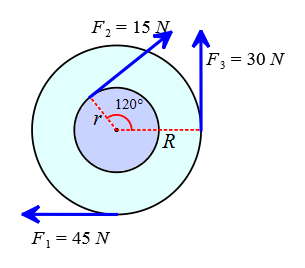
Problem (3): Calculate the net torque about the axle of the wheel through point $O$ perpendicular to the plane of the page, taking $r=12\,\rm cm$ and $R=24\,\rm cm$.
Solution: First, using the definition of torque, we find its magnitude; then, because torque is a vector quantity in physics, we assign a positive or negative sign to it; and finally, we add torques to obtain the net torque about the desired rotation point.
The force $F_1$ rotates the smaller circle with the lever arm $r_{\bot,1}=0.12\,\rm m$ clockwise, so assign a negative to its torque magnitude. \begin{align*} \tau_1&=r_{\bot,1}F_1 \\&=(0.12)(45) \\&=5.4\quad\rm m.N \end{align*} The force $F_2$ also rotates the bigger circle clockwise, whose torque magnitude would be obtained \begin{align*} \tau_2&=r_{\bot,2}F_2 \\&=(0.24)(15) \\&=3.6 \quad \rm m.N \end{align*} And finally, the force $F_3$ rotates the bigger circle counterclockwise, so by convention assign a positive sign to its torque magnitude: \begin{align*} \tau_3&=r_{\bot,3}F_3 \\&=(0.24)(30) \\&=7.2 \quad \rm m.N \end{align*} Now, add torques with their correct signs to get the net torque about the axle of the wheel: \begin{align*} \tau_{net} &=\tau_1+\tau_2+\tau_3 \\ &=(-5.4)+(-3.6)+(7.2) \\&=-1.8\quad \rm m.N \end{align*} The overall sign of the net torque is obtained as negative, telling us that these forces will rotate the wheel about its axle clockwise.
When a force is applied to the rim of a circle or wheel and makes an angle with the horizontal line, the torque about the center of the wheel (or circle) does not depend on this angle.
By definition, the lever arm is the perpendicular distance from the point of application of force to the axis of rotation. In torque problems involving a wheel (or circle) and forces applying to the rim of it, the lever arm is always the radius of the wheel.
My income comes from your generous donations. Please support me.
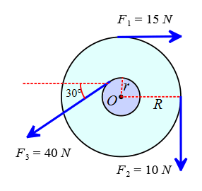
Problem (4): Three forces are applied to a wheel as shown in the figure below. Two forces are tangent to the wheel, while the third forms a $37^\circ$ angle with the tangent to the inner circle. What is the net torque on the wheel due to these three forces about the axle through $O$ perpendicular to the page? Assume that a friction torque of $0.3\,\rm m.N$ opposes the rotation. (take $r=10\,\rm cm$ and $R=20\,\rm cm$)
Solution: Again a wheel and some forces acting on its rim and wanting the net torque about its center.
The forces $F_1$ and $F_2$ rotate the wheel clockwise, which exerts negative torques on the wheel whose magnitudes are found as follows \begin{align*} \tau_1&=r_{\bot,1}F_1 \\&=(0.20)(15) \\&=3\quad \rm m.N \\\\ \tau_2&=r_{\bot,2}F_2 \\&=(0.20)(10) \\&=2\quad \rm m.N \end{align*} The other force $F_3$ that acts at an angle with the rime of the smaller circle apply a positive torque according to the sign conventions for torques (counterclockwise rotation). Its magnitude is \begin{align*} \tau_3&=r_{\bot,3}F_3 \\&=(0.10)(40) \\ &=4\quad\rm m.N \end{align*} Now, sum these torques to find the net torque exerted about the axle of the rotation $O$, being careful not to forget to consider their signs. \begin{align*} \tau_{net}&=\tau_1+\tau_2+\tau_3 \\ &=(-3)+(-2)+(+4) \\ &=-1\quad \rm m.N\end{align*} This is the net torque applied by the external forces that cause the wheel to rotate counterclockwise.
In this question, we are told that the axis of rotation also exerts a friction force, whose corresponding torque has a magnitude of $0.3\,\rm m.N$. This torque, due to a frictional force, opposes the overall rotation of the wheel, which is counterclockwise, so it must be supplied by a positive sign, i.e., $\tau_f=+0.3\,\rm m.N$.
Hence, the total torque with respect to the point $O$ is \[\tau_t=-1+(+0.3)=\boxed{-0.7\,\rm m.N}\]
Problem (5): A person exerts a force of $50\,\rm N$ on the end of an $86-\rm cm$-wide door to open it. What is the magnitude of the torque if the force is applied (a) perpendicular to the door and (b) at an angle of $53^\circ$ to the plane of the door?
Solution: An overhead view of this configuration is depicted below.
Torque is defined as $\tau=rF\sin\theta$, where $r$ is the distance between the point of application of the force and the point of the axis of rotation, $F$ is the applied force, and $\theta$ is the angle between the applied force and the line connecting the force action point and the rotation point.
(a) In this case, the force is applied to the door perpendicularly. The line joining the force action point (say, the doorknob) and the axis of rotation (the hinge's door), which is actually the same $r$, makes a right angle with the force vector as shown in the figure below, so $\theta=90^\circ$.
Substituting the numerical values into the torque formula gives its magnitude as below: \begin{align*} \tau&=rF\sin\theta \\&=(0.86)(50) \sin 90^\circ \\ &=43\quad\rm m.N \end{align*}
(b) in this part, the angle between $r$ and $F$ is $\theta=53^\circ$ as illustrated in the figure below. Thus, the torque associated with this force is found to be \begin{align*} \tau&=rF\sin\theta \\&=(0.86)(50) \sin 53^\circ \\ &=34.4\quad \rm m.N\end{align*} From this torque question, we can understand the physical concept of torque.
You have seen that the same force applied to the door at two different angles can produce two different torques. But what is this meaning?
You can do this yourself at home and see the result.
Certainly, you will notice that opening a door by applying a force perpendicular to its knob is much easier than applying the same force at some angle.
Therefore, we conclude that the greater the torque produced, the easier the door opens.
Problem (6): In the following figure, all rods have the same length and are pivoted at point $O$. Rank in order, from the smallest to largest, the torques.
Solution: First, calculate the torques corresponding to each applied force. Since the length of the rods was not given, take it as $L$.
(a) A force $F$ is applied to the left end perpendicular to the radial line $r$, such forces create maximum torque whose magnitude is \[\tau_a=rF=\boxed{4L}\] (b) In this case, the force $F$ is applied perpendicularly to the middle of the radial line, so the distance between the force action point and the pivot point is $r=\frac L2$ \[\tau_b=rF=4(\frac L2 )=\boxed{2L}\] (c) Here, the line of action of the force makes a $45^\circ$ angle with the radial line, $\theta=45^\circ$. On the other hand, the straight distance between the force action point and the pivot point is $r=L$. Thus, the torque associated with this force is computed as \begin{align*} \tau_c&=rF\sin\theta \\&= (L)(4) \sin 45^\circ \\ &=\boxed{2\sqrt{2}L}\end{align*} (d) In this case, the force is pulling straight out from the pivot point $O$ and making a zero angle, $\theta=0$, with the radial line. Hence, the torque of this force is given by \[\tau_d=rF\sin\theta=L(4) \sin 0^\circ= \boxed{0}\] Such forces as pulling out from or pushing into the pivot point exert zero torque. Now we are in a position to rank the torques from smallest to largest. \[\tau_d <\tau_b < \tau_c <\tau_a\]
Problem (7): A person applies a force of $55\,\rm N$ near the end of a $45-\rm cm$-long wrench.
(a) How should the force be applied to produce the maximum torque?
(b) What is the maximum torque exerted?
Solution: In the preceding question, we found out that a maximum torque acts on a pivot point when these two conditions are met;
(I) The external force applied to a point where it has the maximum distance from the pivot point (or axis of rotation) and
(II) When the angle between the force action point and the radial line, a straight line that connects the force action point and the pivot point, is $90^\circ$.
Here we are told that the force is applied near the end of the wrench, having a maximum distance from the rotation axis, so the first condition is satisfied.
(a) To satisfy the second condition, the force must be applied at the right angle to the line of the wrench.
(b) With this explanation, the maximum torque is found to be \[\tau_{max}=rF=(0.45)(55)=\boxed{24.75\,\rm m.N}\]
Problem (8): Find the magnitude and direction of the net torque on a $2-\rm m$-long rod in each of the following cases as shown.
(a) the center of mass of the rod, about point $C$, and (b) through the point $Q$.
Solution: in each case, first, identify the straight distance $r$ between the force action point, where the force acts on the rod, and the pivot point (or the rotation axis).
Next, find the angle $\theta$ between the force $\vec{F}$ and the line connecting the point of application of the force and the pivot point, which is called the radial line, or position vector $\vec{r}$ in your textbooks.
Combining these into the torque formula, $\tau=rF\sin\theta$, to find its magnitude.
(a) Three forces are acting on the rod and causing a torque about the rod's center of mass. Be careful that the point of application of the force $F_3$ does not have distance from the axis of rotation $C$, so the magnitude $r$ of its position vector $\vec{r}$ is zero, i.e., $r=0$.
Consequently, this force cannot rotate the rod, or in other words, the torque due to this force is zero. The other torques are \begin{align*} \tau_1&=rF\sin\theta \\&=(1)(55) \sin 66^\circ \\&=50.24\quad \rm m.N \\\\ \tau_2&=rF\sin\theta \\&=(1)(40) \sin 27^\circ \\ &=18.16\quad \rm m.N\end{align*} The forces $F_2$ and $F_1$ rotate the rod about point $C$ in a counterclockwise direction, so by sign conventions for torques, a positive sign must be assigned to them. Therefore, the net torque about the center of mass of the rod is \begin{align*} \tau_{net}&=\tau_1+\tau_2+\tau_3 \\ &=50.24+18.16+0 \\&=\boxed{+68.4\quad \rm m.N}\end{align*} Consequently, these three forces, applied at different angles to the rod, create a net torque of $68\,\rm m.N$ about the pivot point $C$ and rotate it in a counterclockwise direction (because of the plus sign in front of the net torque).
(b) We want to solve this part by the method of resolving the applied force into its components parallel and perpendicular to the line that connects the axis of the rotation to the point of application of the force, or radial line (this is the same position vector $\vec{r}$).
In this method, the component $F_{\parallel}$ always exerts no torque since it goes through the axis of rotation and thus has a zero lever arm.
Hence, the only component of the force capable of rotating the body about the axis is $F_{\bot}$ which its corresponding torque will be equal to $\tau=rF_{\bot}$ where $r$ is the distance from the axis to the point of application of the force.
In the following figure, the forces are resolved into $F_{\parallel}$ and $F_{\bot}$. Thus, their exerted torques are found to be \begin{align*} \tau_1&=r_1F_{1,\bot} \\&=(0)(55\sin 66^\circ) \\&=0 \\\\ \tau_2&=r_2F_{2,\bot} \\&=(2)(40\sin 27^\circ) \\&=36.32\quad\rm m.N \\\\ \tau_3&=r_3 F_{3,\bot} \\&=(1)(75\sin 53^\circ) \\&=60\quad \rm m.N \end{align*} As you can see, the force $F_1$ is directed at the rotation axis, so $r=0$. The forces $F_2$ and $F_3$ rotate the rod about the point $Q$ in ccw and cw directions, respectively, resulting in a positive and negative torque.
The torque $\tau_2$ is positive since its corresponding force $F_2$ rotates the rod about the point $Q$ counterclockwise (ccw).
The torque $\tau_3$ should be negative since its corresponding force $F_3$ rotates the rod about $Q$ clockwise. Therefore, the net torque about the axis $Q$ is calculated as \begin{align*} \tau_{net}&=\tau_1+\tau_2+\tau_3 \\&=0+(36.32)+(-60) \\ &=\boxed{-23.68\quad\rm m.N} \end{align*} Consequently, the combined forces produce a negative torque that rotates the rod clockwise.
Problem (9): Calculate the net torque (magnitude and direction) applied to the beam in the following figure about (a) the axis through point $O$ perpendicular to the page and (b) the point $C$ perpendicular to the plane of the page.
Solution: As you found out, there are two equivalent ways to calculate torque due to an applied force. One is using the lever arm concept and applying the torque formula, $\tau=r_{\bot}F$, and the other is using the force components, in which only the perpendicular component creates a torque about an axis, $\tau=rF_{\bot}$.
Here, we want to solve this torque AP Physics 1 question by the method of resolving the applied force and applying the formula $\tau=rF_{\bot}$, where $F_{\bot}=F\sin\theta$ and $\theta$ is the angle the force makes with the radial line.
First of all, resolve the forces along $F_{\parallel}$ and perpendicular $F_{\bot}$ to the radial line, the line connecting the point at which the force applies and the pivot point as depicted in the free-body diagram below.
(a) The extension of the radial force component $F_{\parallel}$ passes straight through the pivot point $C$, so it wouldn't create torque.
The extension of the perpendicular force component $F_{\bot}$ always has some finite distance from the pivot point and thus creates torque. The magnitude of torques is found to be \begin{align*} \tau_1 &=rF_{1,\bot} \\&=(3)(20\sin 30^\circ) \\ &=30\quad \rm n.N \\\\ \tau_2 &=rF_{2,\bot} \\&=(0)(30\sin 53^\circ) \\ &=0 \\\\ \tau_3 &=rF_{3,\bot} \\&=(3)(44\sin 45^\circ) \\ &=92.4\quad \rm n.N \end{align*} Notice that for torque due to the force $F_2$, the angle between $F_2$ and the vertical line is given, not the radial line, which is favored. This force applies straight to the axis of rotation and exerts no torque.
Those were the magnitudes of the torques; now determine their correct signs, which indicate the direction of rotations, since torque is a vector quantity in physics, having both a magnitude and a direction.
The torque $tau_1$ acts to rotate the rod clockwise, so a negative is assigned to it. On the other hand, the torque $tau_3$ rotates the rod counterclockwise, so it must be accompanied by a positive sign according to the convention of signs for torques.
The sum of these torques gives the net torque exerted on the pivot point $C$: \begin{align*} \tau_{net} &=\tau_1+\tau_2+\tau_3 \\ &=(-30)+0+(92.4) \\&=62.4\quad \rm m.N \end{align*} Ultimately, the rod will rotate counterclockwise due to applying these forces since its net torque is positive.
(b) Now, we want to find the net torque due to the same forces but about point $O$. In this case, the force $F_3$ exerts no torque as it passes straight through the axis of the rotation $O$, $\tau_3=0$. The magnitude of the torques of the other forces about point $O$ is calculated as below \begin{align*} \tau_1&=r_1F_{1,\bot} \\&=L(F_1 \sin 30^\circ) \\&=(6)(20\times 0.5) \\&=60\quad \rm m.N \\\\ \tau_2&=r_2F_{2,\bot} \\&=(L/2)(F_2 \sin 53^\circ) \\&=(3)(30\times 0.8) \\&=72\quad \rm m.N \end{align*} Therefore, the net torque about point $O$ by considering the correct sign for each torque (positive torque for counterclockwise and negative for clockwise direction) is \begin{align*} \tau_{net}&=\tau_1+\tau_2+\tau_3 \\ &=(-60)+(+72)+0 \\&=+12\quad\rm m.N\end{align*} Thus, this combination of forces rotates the rod in a counterclockwise direction about point $O$, resulting in a net positive torque.
Overall, from this important problem, we learned that torques must always be calculated with reference to a specific point. In part (a), the torque of $F_2$ was zero about point $C$ but not about point $O$. The same reasoning is also true for the force $F_3$ about these two pivot points.
Therefore, the true statement for describing torques due to some applied forces is "the torque of force $F$ about (or with respect to) point $X$".
Problem (10): Two blocks of mass $m$ are attached to a massless rod that pivots as shown in the figure below. Considering the rod is held initially in the horizontal position and released, what is the net torque (magnitude and direction) on the pivot when it is just released?
Solution: two equal masses are standing on a level rod pivoted at a point. First, calculate the magnitude of torques associated with each mass exerted on the rod, then assign a positive or negative sign to each torque to indicate their direction.
Each mass applies a weight force of $w=mg$ to the rod perpendicularly. According to the sign conventions for torques, the left mass rotates the rod counterclockwise about the pivot point with a positive torque and the right mass clockwise with a negative torque.
The magnitude of each torque is calculated by the general torque equation as below \begin{align*} \tau_1&=rF\sin\theta \\&=\mathcal l_1 (mg) \sin 90^\circ \\&=\mathcal l_1 mg \\\\ tau_2&=rF\sin\theta \\&=\mathcal l_2 (mg) \sin 90^\circ \\&=\mathcal l_2 mg \end{align*} The net torque about the pivot point is the sum of the torques due to the applied forces: \begin{align*} \tau_{net}&=\tau_1+\tau_2 \\&=+\mathcal l_1 mg + (-\mathcal l_2 mg) \\ &=mg( \mathcal l_1-\mathcal l_2) \end{align*} In the last step, $mg$ is factored out. Since the lever arm for $m_2$ is greater than $m_1$ or $\mathcal l_2 >\mathcal l_1$, the net torque about the pivot point will be negative. In other words, this combination of masses on the rod just after releasing leads to a clockwise rotation with respect to the support.
Problem (11): A mechanic is loosening a nut using a $25-\rm cm$-long wrench by applying a force of $20\,\rm N$ at an angle of $30^\circ$ to the end of the handle.
(a) What torque does the mechanic apply to the center of the nut?
(b) In which direction should he exert this force to obtain maximum torque, and with what magnitude?
Solution: The angle between the force applied to the wrench and the radial line is given by $30^\circ$. Here, the distance between the point at which the force acts and the nut (axis of rotation) is $r=0.25\,\rm m$.
(a) Use the general equation for torque, $\tau=rF\sin\theta$, to find its magnitude as follows \begin{align*} \tau&=rF\sin\theta \\ &=(0.25)(20\times \sin 30^\circ) \\&=2.5\quad \rm m.N \end{align*}
(b) Once the applied force is resolved into its radial $F_{\parallel}$ and perpendicular $F_{\bot}$ components, the $F_{\bot}$ points in the counterclockwise direction, so it exerts a positive torque by our sign convention.
Author: Dr. Ali Nemati
Published: Mar 20, 2023
© 2015 All rights reserved. by Physexams.com
AP® is a trademark registered by the College Board, which is not affiliated with, and does not endorse, this website.