Kirchhoff's Law Practice Problems: AP Physics C
This is the most complete and up-to-date article on Kirchhoff's law problems. By practicing these questions, you can easily solve any type of problem from this topic appearing on the AP Physics C exam.
Kirchhoff's Law Problems
Problem (1): Calculate the current in the following circuit using Kirchhoff's loop rule.
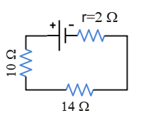
Solution: Although we can use Ohm's law and the concepts of combined resistors to find the current in the following circuit, the intent, here, is to find it using Kirchhoff's loop rule.
According to this rule, the algebraic sum of the potential changes around a closed loop must equal zero, i.e., $\Sigma V_i=0$, where $V_i$ is the potential across each circuit element.
First, consider an arbitrary direction for current, say from the positive terminal through the circuit in the counterclockwise direction. Kirchhoff's loop rules are:
(a) When you cross the resistor in the direction of the assumed current, then $V=-IR$.
(b) When you cross a battery from the negative ($-$) terminal to the positive ($+$) terminal, the potential change is $V=\mathcal E$ where $\mathcal E$ is the battery's emf. In the case of crossing from $+$ to $-$ terminals, we get $V=-\mathcal E$.
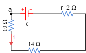
With these rules in mind, we traverse the circuit from point $a$ and back to it in the counterclockwise direction. In solving all Kirchhoff's questions, this point is chosen arbitrarily along the circuit, and we travel the circuit in a direction arbitrarily. \begin{gather*} \Sigma V_i=0 \\\\ -V_{10}-V_{14}-V_2+V_{\mathcal E}=0 \\\\ -iR_{10}-iR_{14}-ir_2+\mathcal E=0 \\\\ -i(10+14+2)+13=0 \\\\ \Rightarrow i=\frac{13}{26}=\boxed{0.5\,\rm A}\end{gather*} We can also check this result using the concept of combined resistors.
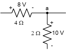
Problem (2): A portion of a circuit is shown below. What are the magnitude and direction of the current in the wire to the right of the junction using Kirchhoff's junction rule?
Solution: Another Kirchhoff's law rule belongs to the junction rule. According to this rule, the algebraic sum of the currents into and out of a given junction must equal zero, i.e., $\Sigma I=0$.
In all circuits, a junction is defined as a point where three or more wires (or conductors) meet.
To use this rule, we adopt the following convention:
Currents flowing into a junction are considered positive, and those flowing out of a junction are negative.
In this problem, the plus and minus signs in the circuit indicate the potential situation across the resistors. $+$ shows a higher potential.
We know that the current flows from higher to lower potential. Thus, the correct direction of the current through each resistor is shown in the figure below.
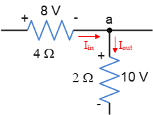
Applying Kirchhoff's junction rule and solving for the unknown current $i_X$ to the right of the junction gives us: \begin{gather*} \Sigma I=0 \\\\ I_{in}+I_{out}=0 \\\\ \frac{V_8}{R_4}+\left(-\frac{V_{10}}{R_2}\right)+i_X=0 \\\\ 2-5+i_X=0 \\\\ \Rightarrow \boxed{i_X=3\,\rm A} \end{gather*} Note that the output of the current using this rule, gives us both the magnitude and direction of the current in that branch of the circuit.
Here, the current is obtained as a positive value, indicating a current flowing into the junction to the left.
Problem (3): What are the magnitude and direction of the current through the $15-\rm \Omega$ resistor using Kirchhoff's loop rule?
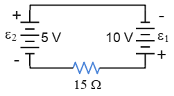
Solution: This Kirchhoff's loop rule problem contains a single-loop circuit in which two batteries oppose each other. Pay attention to solving this question carefully.
We can find the direction of $i$ in the circuit from the given values of emfs. Since $\mathcal E_1$ is greater than $\mathcal E_2$, the battery $1$ controls the direction of the current in the circuit. Thus, the current is clockwise.
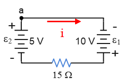
We start from point $a$ and apply the loop rule clockwise, knowing that crossing the resistor in the direction of $i$ gets $V_R=-iR$ and crossing from $-$ to $+$ terminals of a battery yields $V=\mathcal E$. \begin{gather*} \Sigma V=0 \\\\ +\mathcal E_1-iR_{15}+\mathcal E_2=0 \\\\ 10-i(15)+5=0 \\\\ \Rightarrow \boxed{i=1\,\rm A}\end{gather*} The positive sign for $i$ indicates that the assumed current is right.
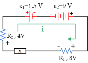
Problem (4): What is the potential difference $\Delta V$ across the unspecified circuit element shown in the circuit below? Does potential increase or decrease through this component when traversing in the direction of the assumed current?
Solution: Kirchhoff's loop rule tells us that the sum of the potential changes around a closed loop in a circuit must be zero, according to the conservation of energy, i.e., $\Sigma V_i=0$, where $V_i$ is the potential change or difference across a circuit element.
To use this rule, first of all, we must arbitrarily assign a direction for the current through the circuit. Then,
(a) Traveling the resistor in the direction of the assumed current leads to a decrease in the potential change across it by $\Delta V_R=-IR$.
(b) Traveling the source of emf $\mathcal E$ (battery) from the negative terminal to the positive terminal gives an increase in the potential change by $\Delta V_{\mathcal E}=+\mathcal E$.
(c) Traveling the source of emf $\mathcal E$ from $+$ terminal to the $-$ terminal leads to a decrease in the potential change by $\Delta V_{\mathcal E}=-\mathcal E$.
With these rules, we start at an arbitrary point, say the upper left corner, and travel the circuit in the assigned direction for the current. \begin{gather*} \Delta V_i=0 \\ V_{\mathcal E_1}+V_{\mathcal E_2}+V_{R_1}+V_X+V_{R_2}=0 \\ -\mathcal E_1+\mathcal E_2 -V_1+V_x-V_2=0 \\ -1.5+9-8+V_x-4=0 \\ \Rightarrow \boxed{V_x=4.5\,\rm V} \end{gather*}
Problem (5): The batteries in the circuit below have negligibly small internal resistances. Find the current through (a) the $30-\rm \Omega$ resistor; (b) the $6-\rm V$ battery; (c) the dissipation rate in resistor $30-\rm\Omega$.
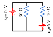
Solution: This is a multiloop circuit consisting of three branches: the left-hand branch $abd$, the right-hand branch $cbd$, and the central branch $bd$. To solve such Kirchhoff's law problems, we must apply loop and junction rules simultaneously and solve the corresponding equations.
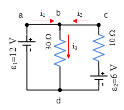
From the polarity of battery $1$, $\mathcal E_1=12\,\rm V$, the correct direction of the current in the left-hand branch is deduced from $a$ to $b$. Similarly, we can find the current in the right-hand branch to be from $c$ to $b$.
At point $b$, the junction rule requires us that in the $bd$ wire the current must be from $b$ to $d$ because there are two other incoming currents and so there must be at least one outgoing flow. As a result, at junction $b$, we have \begin{gather*} \Sigma I=0 \\ i_1+i_2-i_3=0 \\ \Rightarrow \boxed{i_1+i_2=i_3} \end{gather*} Recall that incoming currents, $i_1$ and $i_2$ are considered positive and outgoing current, $i_3$, negative.
In the equation above, there are three unknown currents, so we must have three other independent equations to find them. Starting at point $a$, traversing the circuit clockwise and applying the loop rule to the left loop gives us \begin{gather*} -i_3 R_{30}+\mathcal E_1=0 \\\\ -i_3 (30)+12=0 \\\\ \Rightarrow \boxed{i_3=0.4\,\rm A} \end{gather*} Similarly, starting at $c$ and going counterclockwise the right loop gives \begin{gather*} -i_3 R_{30}+\mathcal E_2-i_2 R_{10}=0 \\\\ -(0.4)(30)+6-i_2 (10)=0 \\\\ \Rightarrow \boxed{i_2=-0.6\,\rm A} \end{gather*} A negative for the current in the Kirchhoff's law problems indicates that the assumed direction of the current was chosen wrongly. Therefore, the correct direction for $i_2$ is from $b$ to $c$. Now use the equation obtained using the junction rule above, to find the current in the $bd$ wire \begin{gather*} i_1+i_2=i_3 \\\\ i_1+(-0.6)=0.4 \\\\ \Rightarrow \boxed{i_1=1.0\,\rm A} \end{gather*} Keep in mind that we do not correct the negative sign for current $i_2$ until the end of the calculation when all currents are found. As the last step, we reverse the sign of those wrongly obtained currents. Therefore, \[\boxed{i_2=0.6\,\rm A}\]
(a) The current in the $30-\rm \Omega$ resistor is $i_3=0.4\,\rm A$.
(b) In the previous part, we found that the current $i_2$ in the right branch circles in a clockwise direction. Therefore, the current through the $6-\rm V$ battery is $i_2=0.6\,\rm A$ from the positive terminal to the negative terminal inside the battery.
This weird direction for the current in the right loop containing battery $2$ from $-$ terminal to the $+$ terminal in the wire (outside the battery) tells us that this battery must be charged by the other battery $\mathcal E_1$.
(c) The time rate at which energy is dissipated as thermal energy in a resistor is given by $P_R=Ri^2$, where $i$ is the current through the resistor. The current through the $30-\rm \Omega$ resistor is found in part (a) to be $i_3=0.4\,\rm A$. Therefore, \begin{align*} P_R&=Ri^2 \\\\ &=(30)(0.4)^2 \\\\ &=\boxed{4.8\,\rm W}\end{align*} The time rate of energy is called power, with the SI unit of the watt.
Problem (6): In the circuit below, the ideal batteries have emfs $\mathcal E_1=100\,\rm V$ and $\mathcal E_2=50\,\rm V$ and the resistances are $R_1=5\,\rm \Omega$ and $R_2=8\,\rm \Omega$. If the point $P$ has a potential of $75\,\rm V$, what is it at $Q$?
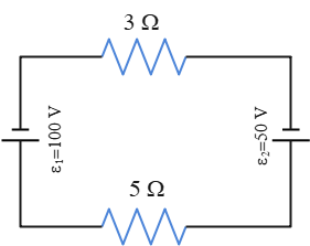
Solution: This single-loop circuit contains two batteries that oppose each other, meaning the same terminals are connected to each other and send current in opposite directions in the resistor.
We assume the current is provided by the greater battery in the counterclockwise direction. According to Kirchhoff's loop rule, the sum of the potential changes around the loop must be zero, i.e., $\Sigma V=0$. Let us start at point $a$ and travel along the circuit counterclockwise back to the initial point $a$ (because we want a closed loop to apply the loop rule).
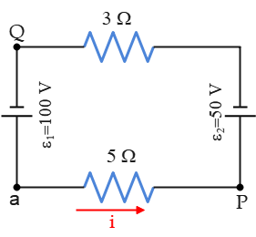
Recall from Ohm's law problems that $\Delta V=IR$. Applying Kirchhoff's and Ohm's laws gives \begin{gather*} \Sigma V=0 \\\\ -iR_5-\mathcal E_2-iR_3+\mathcal E_1=0 \\\\ -i(5)-50-i(3)+100=0 \\\\ \Rightarrow \boxed{i=12.5 \,\rm A} \end{gather*} A positive sign for the current indicates that the assumed direction for that current is right. As a learning point, we want to traverse the circuit in the opposite direction of our assumed current by going clockwise from point $a$ \begin{gather*} \Sigma V=0 \\\\ -\mathcal E_1+iR_3+\mathcal E_2+iR_5=0 \\\\ -100+i(3)+50+i(5)=0 \\\\ \Rightarrow \boxed{i=12.5 \,\rm A} \end{gather*} Again, the same result. This tells us that traversing the circuit clockwise or counterclockwise is arbitrary, but once you made it, you must be consistent with the conventions about plus and minus signs.
In this part, the potential changes between two arbitrary points in the circuit are asked. In these situations, we apply Kirchhoff's loop law but don't set it equal to zero. Starting at point $P$ and arbitrarily traveling counterclockwise through the circuit, find the potential changes. We find \begin{gather*} V_P-\mathcal E_2-iR_3=V_Q \\ 100-50-(12.5)(3)=V_Q \\ \Rightarrow \boxed{V_Q=12.5\,\rm V} \end{gather*} This tells us that the potential at point $Q$ is as much as $10\,\rm V$ higher than the potential at point $P$.
Problem (7): What is the potential difference between points $a$ and $b$ in the following circuit? Each resistor has $R=150\,\rm \Omega$ and each ideal battery is $9\,\rm V$.
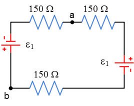
Solution: First of all, find the current in the circuit. We can find it using Kirchhoff's loop rule around the loop or use the standard formula below (which is obtained by applying loop rule) \[i=\frac{\mathcal E_1+\mathcal E_2}{R_1+R_2+\cdots}\] We can use this formula once there is a single-loop circuit containing two batteries with opposite terminals connected to each other. Verify this formula by writing the loop rule for this circuit. Thus, \[i=\frac{9+9}{150+150+150}=0.04\,\rm A\] To find the potential difference between the two given points, start at one point, say $a$, sum the potential changes across each circuit component according to the loop rule conventions, and set it to the final point, here $b$.
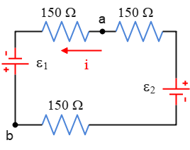
Here, the proper current in the circuit is counterclockwise, starting from the positive terminal of one battery and ending at the negative terminal of the other battery. Now, we travel the circuit in the direction of the current. \begin{gather*} V_a-iR+\mathcal E_1=V_b \\ V_a-(0.04)(150)+9=V_b \\ \Rightarrow \boxed{V_a-V_b=-3\,\rm V} \end{gather*} This tells us that the potential at point $a$ is as much as $3\,\rm V$ lower than the potential at point $b$.
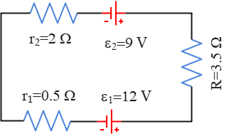
Problem (8): What are the terminal voltages in each battery in the circuit below?
Solution: one of the common terms appearing in Kirchhoff's rule problems of the AP Physics C exam is finding the terminal voltage of a battery.
Each real battery in an electric circuit has a small internal resistance, symbolized by $r$. On the other hand, the work the battery does on a unit charge to move it from its low-potential terminal ($-$) to its high-potential terminal ($+$) is called the emf ($\mathcal E$) of that battery.
As charges travel from the negative to the positive terminal inside the battery, they gain potential $\mathcal E$ but lose potential $-ir$ due to the presence of internal resistance. As a result, the net potential difference across the battery from the outside user is determined as \[\Delta V_{bat}=\mathcal E-ir\] Where $i$ is the current through the battery.
Now back to the original question. To find the terminal voltage of each battery, the current flowing through it must first be determined. We want to find the magnitude and direction of the current through this circuit without any consideration of the greater or smaller emfs of the batteries.
For this circuit, blindly choose a current direction and apply Kirchhoff's loop law. Start at point $a$, travel the circuit clockwise, and then return to the initial point $a$. The loop's rule around this loop gives \begin{gather*} \Sigma V=0 \\\\ -iR-\mathcal E_1-ir_1-ir_2+\mathcal E_2=0 \\\\ -i(R+r_1+r_2)-\mathcal E_1+\mathcal E_2=0 \\\\ \Rightarrow i=\frac{\mathcal E_2-\mathcal E_1}{R+r_1+r_2} \end{gather*} This is a general formula for the current in a single-loop circuit containing two batteries with opposing terminals, which can be used for simplicity in the AP Physics C exam.
Substituting the numerical values into this get \begin{align*} i&=\frac{\mathcal E_2-\mathcal E_1}{R+r_1+r_2} \\\\ &=\frac{9-12}{3.5+2+0.5} \\\\ &=\boxed{-0.5\,\rm A} \end{align*} Recall that a negative obtained for current in all Kirchhoff's law problems indicates that the initially chosen direction for the current was wrong. Its magnitude is right.
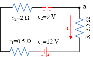
Thus, a $0.5-\rm A$ current passes through the circuit counterclockwise.
The terminal voltage, $\Delta V=\mathcal E-ir$, for each battery is calculated as below \begin{align*} \Delta V_1&=\mathcal E_1-ir_1 \\ &=12-(0.5)(2) \\&=\boxed{11\,\rm V} \\\\ \Delta V_2 &=\mathcal E_2-ir_2 \\ &=9-(0.5)(0.5) \\ &=\boxed{8.75\,\rm V} \end{align*} These are the real values that you can measure using a voltmeter connected across the battery's terminals.
Problem (9): In the circuit shown below, what is the magnitude of the emf's of $\mathcal E_1$ and $\mathcal E_2$?
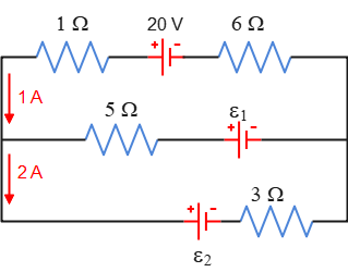
Solution: In this problem, two currents are known at junction $a$ as shown in the figure below.
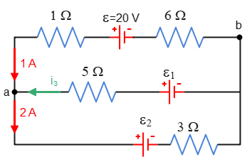
Choose an arbitrary direction for the current in the wire $ac$ as to the left into the junction $a$. Applying the junction rule and solving for $i_3$, gives \begin{gather*} I_{in}=I_{out} \\ i_1+i_3=i_2 \\ 1+i_3=2 \\ \Rightarrow \boxed{i_3=1\,\rm A} \end{gather*} Thus, a $1-\rm A$ current is flowing from $c$ to $a$ in the middle branch through $\mathcal E_1$.
Starting at an arbitrary point, say $b$, and arbitrarily going the upper loop in the counterclockwise direction, giving \begin{gather*} -i_1 R_6 +\mathcal E-i_1 R_1+i_3 R_5-\mathcal E_1=0 \\ -i_1 (R_6+R_1)+\mathcal E+i_3 R_5-\mathcal E_1=0 \\ (-1)(6+1)+20+(1)(5)-\mathcal E_1=0 \\ \Rightarrow \boxed{\mathcal E_1=18\,\rm V} \end{gather*} In a similar way, start at an arbitrary point, say $b$, traverse the big loop in the counterclockwise direction, and apply the loop rule giving \begin{gather*} -i_1 R_6 +\mathcal E-i_1 R_1-\mathcal E_2- i_2 R_3=0 \\ -i_1 (R_6+R_1)+\mathcal E-\mathcal E_2-i_2 R_3=0 \\ -(1)(6+1)+20-\mathcal E_2-(2)(3)=0 \\ \Rightarrow \boxed{7\,\rm V} \end{gather*}
Problem (10): Find the magnitudes and directions of the currents through each resistor $R_1$ and $R_2$ in the circuit shown below. The batteries are ideal batteries.
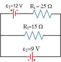
Solution: Ideal battery means it has no internal resistance, $r=0$. First of all, choose arbitrarily a junction, say $c$, and assign arbitrarily incoming and outgoing currents to it as shown in the figure below. Note that all currents can't be merely incoming or outgoing.
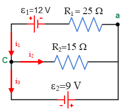
Here, we have chosen two incoming currents and one outgoing current. Now start at an arbitrary point along the circuit, say $a$, arbitrarily traverse the top loop in the counterclockwise direction, and apply the loop rule, obtaining \begin{gather*} \Sigma V=0 \\ -i_1 R_1+\mathcal E_1-i_2 R_2=0 \\ -25i_1+12-15i_2=0 \end{gather*} Repeat the above process for the bottom loop. Start arbitrarily at a point, say $c$, and traverse the loop arbitrarily in the clockwise direction, obtaining \begin{gather*} -i_2 R_2 -\mathcal E_2=0 \\ -15i_2-9=0 \\ \Rightarrow i_2=-0.6\,\rm A \end{gather*} The minus sign tells us that our arbitrary choice of direction for $i_2$ is wrong. As an important note, we will not correct it until the end of the calculation of all currents.
Substituting it into the equation for the top loop gives the current $i_1$ as \begin{gather*} -25i_1+12-15i_2=0 \\ -25i_1+12-15(-0.6)=0 \\ \Rightarrow \boxed{i_1=0.84\,\rm A} \end{gather*} The positive answer obtained for $i_1$ indicates that the arbitrarily chosen direction for that current is correct. Now, as the last step, we correct the sign for $i_2$ and reverse its direction to the left in this wire. Therefore, $\boxed{i_2=0.6\,\rm A}$.
A shorter way to find $i_1$: Start arbitrarily at point $a$ and arbitrarily traverse the bigger loop in the counterclockwise direction. It gives us \begin{gather*} \Sigma V=0 \\ -i_1 R_1-\mathcal E_1+\mathcal E_2=0 \\ -25i_1+12+9=0 \\ \Rightarrow \boxed{i_2=0.84\,\rm A} \end{gather*}
Summary:
In this article, we tried to solve some problems on Kirchhoff's loop and junction laws. Kirchhoff's laws are:
Junction rule: The algebraic sum of the incoming and outgoing currents at a junction must be zero, i.e., $\Sigma I=0$. Currents flowing into a junction are considered positive, and those that leave the junction are negative. This rule is based on the conservation of electric charge.
Loop law: The algebraic sum of the potential changes around any loop must be zero, i.e., $\Sigma V=0$. This rule is based on the conservation of energy.
Author: Dr. Ali Nemati
Published: February 26, 2023
© 2015 All rights reserved. by Physexams.com
AP® is a trademark registered by the College Board, which is not affiliated with, and does not endorse, this website.