AP Physics C: Circuits Practice Problems with Answers
Here, a collection of electric circuit problems is presented and solved. These problems encompass various configurations of capacitors, resistors, and electric power within a DC circuit.
Working through these problems and their solutions will provide ample practice on the topic of circuits for the AP Physics C exam.
By the way, if you’re preparing for the AP Physics 1 exam, feel free to download this comprehensive AP formula sheet. It’s the ultimate resource you need!
Circuit Practice Problems
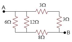
Problem (1): In the circuit below, find the equivalent resistance between points $A$ and $B$.
Solution: One common question in circuit practice problems is determining the equivalent resistance of a circuit.
Remember, when two resistors are in series, their equivalent resistance ($R_{eq}$) is simply the sum of their resistance: $R_{eq}=R_1+R_2$. In contrast, for resistors in parallel, the reciprocal of the equivalent resistance is the sum of the reciprocals of their individual resistances: $\frac{1}{R_{eq}}=\frac{1}{R_1}+\frac{1}{R_2}$.
The two $3-{\rm \Omega}$ resistors are in series, so their equivalent resistance is \[R_{3,3}=R_3+R_3=3+3=6\,{\rm \Omega}\] It's evident that resistors of $12\,{\rm \Omega}$ and $6\,{\rm \Omega}$ are in parallel, so their effective or equivalent resistance is \begin{align*}\frac{1}{R_{12,6}}&=\frac{1}{R_{12}}+\frac{1}{R_6}\\\\&=\frac{1}{12}+\frac{1}{6}=\frac{1+2}{12}\\\\\Rightarrow R_{12,6}&=4\quad{\rm \Omega}\end{align*} Now, $R_{12,6}$ is in series with the resistor of $8\,{\rm \Omega}$ which both have a effective resistance of \[R_{12,6,8}=R_{12,6}+R_8=4+8=12\,{\rm \Omega}\] In the end, we are left two resistors of $12\,{\rm \Omega}$ and $6\,{\rm \Omega}$, which are placed in parallel in the circuit (Because each is positioned on one side of points $A$ and $B$). Thus, the overall resistance of the circuit is determined as follows: \begin{align*}\frac{1}{R_{eq}}&=\frac{1}{R_{3,3}}+\frac{1}{R_{12,6,8}}\\\\&=\frac{1}{12}+\frac{1}{6}=\frac{1+2}{12}\\\\\Rightarrow R_{eq}&=4\quad{\rm \Omega}\end{align*} Note: For two resistors, ($R_1$) and ($R_2$), connected in parallel, the equivalent resistance ($R_{eq}$) can be calculated without resorting to reciprocal values. The formula is straightforward and given by: \[\boxed{R_{eq}=\frac{R_1 \times R_2}{R_1+R_2}}\] This equation simplifies the process of determining the total resistance in a parallel circuit configuration.
Problem (2): The equivalent resistance between points $a$ and $b$ is $40\,{\rm \Omega}$ in the following electric circuit. If resistors $R$ are equal, find their value.
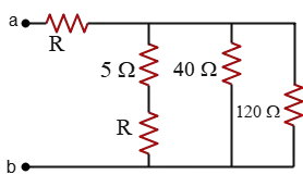
Solution: When two resistances, $120\,{\rm \Omega}$ and $40\,{\rm \Omega}$, are in parallel, we can simplify the circuit by replacing them with their equivalent resistance of two parallel resistors as follows: \[R_{120,40}=\frac{R_1 R_2}{R_1+R_2}=\frac{120\times 40}{120+40}=30\,{\rm \Omega}\] Two resistors $5\,{\rm \Omega}$ and $R$ in the leftmost vertical branch are in series, so their equivalent resistance is $R_{R,5}=R+5$. These two latter equivalent resistances ($R_{120,40}$ and $R_{R,5}$) are also in parallel having an effective resistance of \[\frac{30\times (R+5)}{30+(R+5)}=\frac{30R+150}{R+35}\] In the end, this resistance is placed in series with the $R$ resistor next to the $a$ point. Thus, the overall resistance of the circuit is obtained as \[R_{eq}=R+\frac{30\times (R+5)}{30+(R+5)}\] Setting this equal to $40\,{\rm \Omega}$ and Solving for $R$, we get the value of the unknown resistor. With some rearranging and manipulation, we get the following quadratic equation: \begin{gather*} R+\frac{30R+150}{R+35}=40 \\\\ \frac{R(R+35)+30R+150}{R+35}=40 \\\\ \Rightarrow 40R+1400=R^2+35R+30R+150 \\\\ \Rightarrow R^2+25R-1250=0 \end{gather*} To solve the quadratic equation $ax^2+bx+c=0$ where $a,b,c$ are some constants, use the following equation \[x=\frac{-b\pm\sqrt{b^2-4ac}}{2a}\] In this case, $a=1,b=25,c=-1250$, substituting these numerical values into the above equation, we obtain two solutions as \[R=\frac{2(1)\pm\sqrt{25^2-4(1)(-1250)}}{2(1)}\] The plus sign gives $\boxed{R=25\,{\rm \Omega}}$ and the minus sign would yield $R=-50\,{\rm \Omega}$, which is not physically meaningful, as resistance cannot be negative.
Problem (3): In the following circuit, how much must $R_3$ be so that the equivalent resistance between $A$ and $B$ is $R_1$?
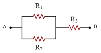
Solution: Resistors $R_1$ and $R_2$ are in parallel, so their equivalent resistance can be obtained by reciprocal-sum rule or the equation below \[R_{12}=\frac{R_1 \times R_2}{R_1+R_2}\] The resulting resistance is in series with resistor $R_3$. Therefore, the total equivalent resistance of the circuit is \[R_{eq}=R_{12}+R_3\] It is given that the equivalent resistance of the circuit is $R_1$, so we set $R_{eq}=R_1$ in the above equation and solve for $R_1$: \begin{gather*} R_1 =\frac{R_1 \times R_2}{R_1+R_2}+R_3 \\\\ \Rightarrow R_3=R_1-\frac{R_1 \times R_2}{R_1+R_2}=\frac{R_1^2+R_1 R_2-R_1 R_2}{R_1+R_2} \\\\ \Longrightarrow \boxed{R_3=\frac{R_1^2}{R_1+R_2}}\end{gather*}
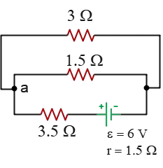
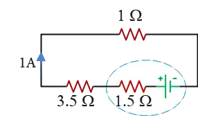
Problem (4): In the circuit below, how much current passes through the $1.5-{\rm \Omega}$ resistor?
Solution: To solve this type of problem, we first determine the total equivalent resistance of the circuit. Then, using Ohm’s law, we calculate the total current supplied by the battery.
Two resistors, $3\,{\rm \Omega}$ and $1.5\,{\rm \Omega}$, are in parallel. Their equivalent resistance is calculated as follows: \[R_{eq}=\frac{3\times 1.5}{3+1.5}=1\,{\rm \Omega}\] This effective resistor is then in series with the circuit's remaining external resistance of $3.5\,{\rm \Omega}$. With this simplification, the circuit involves the resistances of $1\,{\rm \Omega}$, $3.5\,{\rm \Omega}$, and the internal resistance of the battery. Thus, we combine them to find the total equivalent resistance of the circuit: \[R_t=1+3.5=4.5\,{\rm \Omega}\]
All these resistors are in series with each other, so the same current flows through each one. This current is also the total current delivered by the battery into the circuit. But what is the magnitude of this current?
When a circuit is connected to a source of emf (battery), the total current through the battery is determined by the following formula: \[I_t=\frac{\mathcal{E}}{r+R_{eq}}=\frac{6}{1.5+4.5}=1\,{\rm A}\] Therefore, a current of ($1\,\rm A$) flows through each resistor. The next step is to calculate the current through the $1.5\,{\rm \Omega}$ resistor, which is part of the combined $1\,{\rm \Omega}$ resistor.
Since the ($1.5\,{\rm \Omega}$) and ($3\,{\rm \Omega}$) resistors are in parallel, they have the same voltage across them, denoted as ($V_3=V_{1.5}$). Using Ohm’s law, we establish a relationship between the currents through these two resistors: \begin{gather*} V_3=V_{1.5} \\\\ I_3 R_3=I_{1.5}R_{1.5}\\\\ 3I_3=1.5I_{1.5} \\\\ \Rightarrow \boxed{I_3=\frac 12 I_{1.5}}\end{gather*} The $1-{\rm A}$ total current supplied by the battery when reaches the junction $a$, splits into the two currents $I_3$ and $I_{1.5}$. Their sum must equal the total current (i.e., $I_t=I_3+I_{1.5}$).
In this case, we have $I_{1.5}+I_3=1\,{\rm A}$. Substituting the relationship between $I_3$ and $I_{4.5}$ into this equation, we find: \begin{gather*} I_{1.5}+\frac 12 I_{1.5}=1 \\\\ \Rightarrow (1.5)I_{1.5}=1 \\\\ \Rightarrow I_{1.5}=\frac{1}{1.5}=\frac 23 \,{\rm A}\end{gather*} Thus, the current through the $1.5\,{\rm \Omega}$ resistor is $\frac 23 \,{\rm A}$.
Further reading:
Ohm's law Practice problems with solutions
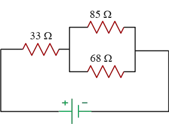
Problem (5): The $33-{\rm \Omega}$ resistor dissipates $0.8\,{\rm W}$ in the circuit shown below. Find the voltage across the battery.
Solution: The battery voltage is unknown. By knowing the total current flowing from the battery and the equivalent resistance of the circuit, we can determine the battery's voltage using Ohm's law, represented by $V_t=I_t R_t$.
The power dissipated by a resistor is calculated using the following formulas: \[P=R i^2=\frac{V^2}{R}=Vi\] where $V$ is the voltage across the resistance and $i$ is the current flowing through it.
In this circuit, the $33-{\rm \Omega}$ resistor is connected directly to the battery, ensuring that all the current delivered by the battery also flows through it. Consequently, the current through this resistor is equal to the total current of the circuit.
Applying the power formula, $P=R i^2$, and solving for $i$, we find the current flowing from the $33-{\rm \Omega}$ resistor as follows: \[i=\sqrt{\frac{P}{R}}=\sqrt{\frac{0.8}{33}}=0.156\,{\rm A}\] This value represents the total current flowing from the battery, $I_t=0.156\,{\rm A}$. The next step is to calculate the equivalent resistance of the circuit.
The $68\,{\rm \Omega}$ and $85\,{\rm \Omega}$ resistors are arranged in parallel, yielding an equivalent resistance calculated as: \[R_{eq}=\frac{68\times 85}{68+85}=37.7\,{\rm \Omega}\] This new resistor is then placed in series with the $33-{\rm \Omega}$ resistor, resulting in a total equivalent resistance for the circuit of \[R_t=33+37.7=70.7\quad {\rm \Omega}\] With the total current and resistance of the circuit known, we can find the voltage across the battery using Ohm’s law: \[V_t=I_t R_t=0.156\times 70.7=11.029\,{\rm V}\] Which can be approximated to $11.03\,\rm V$.
Problem (6): In the circuit shown below, the $2-{\rm \Omega}$ resistor dissipates a power of $18\,{\rm W}$ in the circuit. What is the voltage between points $A$ and $B$?
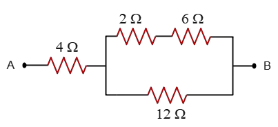
Solution: The voltage between points $A$ and $B$ is the sum of voltages across $4-{\rm \Omega}$ resistor and the loop. \[V_{AB}=V_{cd}+V_{ef}\] Our task is to find these two unknown voltages.
The resistors $2-{\rm \Omega}$ and $6-{\rm \Omega}$ are in series, so the currents through them are the same. Given the power dissipated by $2-{\rm \Omega}$ resistor and using the power formula $P=Ri^2$, we can find the current flowing from this resistor \[i=\sqrt{\frac{P}{R}}=\sqrt{\frac{18}{2}}=3\,{\rm A}\] Thus, $I_2=I_6=3\,{\rm A}$. The equivalent resistance of these two is \[R_{2,6}=R_2+R_6=2+6=8\,{\rm \Omega}\] The total current and equivalent resistance of the upper branch are known, so using Ohm's law, we can find the voltage across this branch as \[V_{up}=IR=3\times 8=24\,{\rm V}\] The lower branch also has the same voltage as the up branch according to this rule that the voltages across parallel branches are the same. Therefore, \[V_{upper}=V_{lower}=V_{ef}=24\,{\rm V}\]
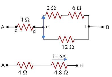
Given the voltage of the lower branch, one can find the current through the $12-{\rm \Omega}$ resistor. \[i_{12}=\frac{V}{R_{12}}=\frac{24}{12}=2\,{\rm A}\] The sum of currents flowing from the upper and lower branches (parallel branches) gives us the total current before splitting into those (junction rule in Kirchhoff's rule). Hence, \[i_{ef}=i_{upper}+i_{lower}=3+2=5\,{\rm A}\] This is the current flowing also from the $4-{\rm \Omega}$, since it is placed in series with the equivalent resistance between points $e$ and $f$ (find yourself $R_{ef}=?$).
Therefore, using Ohm's law the voltage $V_{cd}$ is calculated as \[V_{cd}=i_{cd}R_4=5\times 4=20\,{\rm V}\] Hence, the voltage across the points $A$ and $B$ is \[V_{AB}=V_{cd}+V_{ef}=20+24=44\,{\rm V}\]
Further Reading: Kirchhoff's law solved problems for the AP Physics C exam
Problem (7): In the circuit shown below, the voltage drop across the internal resistance and the $2.5-{\rm \Omega}$ resistor are $0.25\,{\rm V}$ and $1.25\,{\rm V}$, respectively. Find the emf and internal resistance of the battery.

Solution: In a circuit, the potential drop across the battery's internal resistance is $V_r=Ir$, and that across the external resistor is $V_R=IR$, where $I$ represents the total current flowing through the circuit.
Using these two facts and their given numerical values, we can find their ratio \begin{align*} \frac{V_r}{V_R}&=\frac{Ir}{IR}\\\\ \frac{0.25}{1.25}&=\frac{r}{2.5}\\\\ \Rightarrow r&=0.5\,{\rm \Omega}\end{align*} Thus, the internal resistance of the battery is $\boxed{r=0.5\,{\rm \Omega}}$.
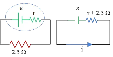
In a simple circuit involving a source of emf with internal resistance $r$ and an external resistance $R$, the current delivered by the battery is found using the formula \[I=\frac{\mathcal E}{r+R}\] Rearranging this, and substituting the given values, we have \begin{align*} \mathcal{E}&=IR+Ir\\\\ &=V_R+V_r \\\\ &=1.25+0.25\\\\&=1.5\quad {\rm V}\end{align*} Thus, the emf of the battery is $\boxed{\mathcal{E}=1.5\,{\rm V}}$
Problem (8): In the circuit below, when the switch is opened, the voltmeter shows $12\,{\rm V}$, and when it is closed, the voltmeter reading is $10\,{\rm V}$. What are the emf and the internal resistance of the battery?
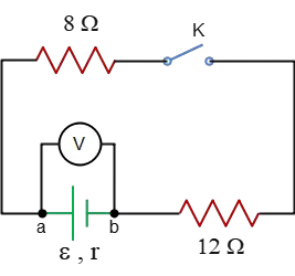
Solution: Remember that in a circuit including a source of emf with an internal resistance of $r$ and an equivalent resistance of $R_{eq}$ due to other resistances external to the battery, the total current flowing through the circuit is found by the formula below \[I=\frac{\mathcal{E}}{r+R_{eq}}\] Here, the voltmeter is connected across the terminals of the battery, so it shows the battery's terminal voltage. Always, the terminal voltage is given by $\Delta V=\mathcal{E}-Ir$, where $I$ is the total current through the circuit.
In this circuit, when the switch $K$ is opened, there is no closed loop including the battery (except the loop with the voltmeter), so the current through the circuit is zero, $I=0$. Substituting this into the terminal voltage formula above, the emf of the battery is obtained \[V_{ab}=\mathcal{E}-Ir \Rightarrow V_{ab}=\mathcal{E}=12\,{\rm V}\] When the switch $K$ is closed, the two other external resistors come into play. These two resistors are in series with each other, so their equivalent resistance is the sum of each. \[R_{eq}=R_8+R_{12}=8+12=20\,{\rm \Omega}\] In this case, the terminal voltage or voltmeter reading is \[V_{ab}=\mathcal{E}-Ir \Rightarrow \boxed{10=12-Ir}\] $I$ is also found using the formula below \[I=\frac{\mathcal{E}}{r+R_{eq}}=\frac{12}{r+20}\] Substituting this into the above boxed equation, and solving for $r$, we have \begin{gather*} 10=12-\left(\frac{12}{r+20}\right)r \\\\ \frac{12r}{r+20}=12-10=2\\\\ 6r=r+20 \\\\ 5r=20 \\\\ \Rightarrow r=4\,{\rm \Omega}\end{gather*}
Problem (9): What happens to the readings of the ammeter and voltmeter for the circuit below when the switch $S$ is closed?
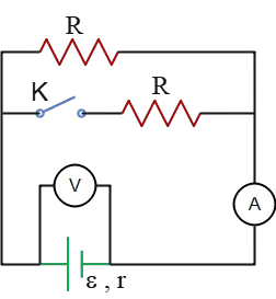
Solution: The ammeter reads the total current $I$ through from the battery or the circuit, whose value is found by \[I=\frac{\mathcal{E}}{r+R_{eq}}\] The voltmeter also reads the terminal voltage across the battery whose value is given by \[V_{ab}=\mathcal{E}-Ir\] where $r$ is the internal resistance of the battery.
When the switch is opened, the middle branch is removed from the circuit, so the equivalent resistance of the circuit equals $R_{eq}=R$. Correspondingly, the current in this case is \[I_O=\frac{\mathcal{E}}{r+R_{eq}}=\frac{\mathcal{E}}{r+R}\] where $I_O$ is the current when the switch is open. By opening the switch, the voltmeter reading is also found as \begin{align*} V_O&=\mathcal{E}-I_O r\\\\ &=\mathcal{E}-\left(\frac{\mathcal{E}}{r+R}\right)r \\\\&=\frac{\mathcal{E}R}{R+r}\end{align*} Now we turn to the case of closing the switch $S$. In this case, the equivalent resistance is \[R_{eq}=\frac{R\times R}{R+R}=\frac R2\] Since the resistors are in parallel. The ammeter shows the total current flowing from the battery whose value is \[I_C=\frac{\mathcal{E}}{r+R_{eq}}=\frac{\mathcal{E}}{r+R/2}\] On the other side, as mentioned, the voltmeter indicates the voltage across the battery or terminal voltage with the following value \begin{align*} V_C&=\mathcal{E}-I_C r\\\\ &=\mathcal{E}-\left(\frac{\mathcal{E}}{r+R/2}\right)r \\\\&=\frac{\mathcal{E}R}{R+2r}\end{align*} Now we compare the currents and voltages before and after closing the switch $K$: \begin{gather*} \frac{\mathcal{E}}{r+R/2}> \frac{\mathcal{E}}{r+R} \\\\ \Rightarrow \boxed{I_C > I_O} \\\\ \frac{\mathcal{E}R}{R+r} > \frac{\mathcal{E}R}{R+2r} \\\\\Rightarrow \boxed{V_O > V_C} \end{gather*}
Problem (10): (a) Four $3.2-{\rm \mu F}$ capacitors are connected in series. What is the equivalent capacitance? (b) Assuming now they are connected in parallel, what is their equivalent capacitance?
Solution: (a) When a number of capacitors are connected in series, say $C_1, C_2, C_3,\cdots$, their equivalent capacitance is given by the following formula \[\frac{1}{C_{eq}}=\frac{1}{C_1}+\frac{1}{C_2}+\frac{1}{C_3}+\cdots\] Therefore, in this case, the equivalent capacitance is \[\frac{1}{C_{eq}}=\frac{1}{3.2}+\frac{1}{3.2}+\frac{1}{3.2}+\frac{1}{3.2}=\frac{4}{3.2}\] By inverting, we have $C_{eq}=0.8\,{\rm \mu F}$.
(b) When those capacitors are in parallel, their equivalent capacitance becomes \[C_{eq}=C_1+C_2+C_3+\cdots\] Thus, in this case, the equivalent capacitance is \[C_{eq}=4(3.2)=12.8\,{\rm \mu F}\]
Problem (11): In the following circuit, what is the potential difference across the capacitor?
a. 8V b. 10V c. 6V d. 15V
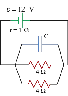
Solution: As can be seen from the circuit, the two $4-{\rm \Omega}$ resistors are in parallel, so we compute their combined resistance and replace them with that. \[R_{eq}=\frac{R_1 R_2}{R_1+R_2}=\frac{4\times 4}{4+4}=2\,{\rm \Omega}\] Note that when a fully charged capacitor is present in an electric circuit, that branch acts as an open circuit, which means the current no longer flows through it. Because, in practice, the capacitor behaves like a resistor with infinite resistance.
On the other side, the current delivered by a source of emf (battery) with internal resistance $r$ and external resistance $R_{eq}$ finds \[I=\frac{\mathcal{E}}{r+R_{eq}}=\frac{12}{1+2}=4\,{\rm A}\] All this current flows through the equivalent resistance of $2\,{\rm \Omega}$. Given that, we can find the potential drop across this combined resistor, using Ohm's law, as \[V=IR=4\times 2=8\,{\rm V}\] Now pay attention to this fact that the capacitor and $2-{\rm \Omega}$ equivalent resistance are in parallel which means the voltage across the capacitor is the same as the voltage across the resistor (i.e., $V_C=V_{2R}$).
Hence, the potential (voltage) difference across the capacitor is $\boxed{8\,{\rm V}}$.
Problem (12): In the circuit diagram shown below, how much charge is stored on the plates of the capacitor?
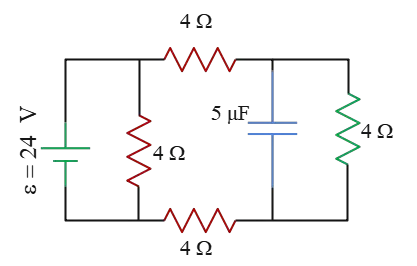
Solution: The charge stored on the plates of a capacitor is related to the voltage across it by $Q=C\Delta V$. The capacitance of the capacitor is known; the only thing that we must find is the potential drop (voltage) across it.
On the other side, you can see that the capacitor is connected in parallel with the $4-{\rm \Omega}$ resistor, which means that the voltage difference across the capacitor is the same as the resistor. So, our task is to find the voltage across the $4-{\rm \Omega}$ resistor, $\Delta V_4=IR$, which is subsequently needed to find the current through that resistor.
As a rule of thumb, ignore that branch of the circuit that includes the capacitor since the capacitors in an electric circuit (when it is fully charged) act as a resistor with an infinite resistor and open the circuit.
With this long introduction, let's move on to solving the problem.
By ignoring the capacitor, the three $4-{\rm \Omega}$ resistors are in series with a equivalent resistance of $R_{eq}=3(4)=12\,{\rm \Omega}$. This new resistor is in parallel with the other $4-{\rm \Omega}$ resistor in the middle branch.
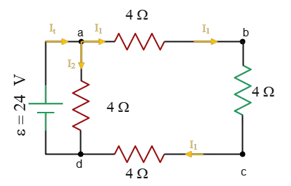
Thus, the total equivalent resistance of the circuit is \[R_t=\frac{R_1 R_2}{R_1+R_2}=\frac{4\times 12}{4+12}=3\,{\rm \Omega}\] The total current flowing through the circuit is \[I_t=\frac{\mathcal{E}}{r+R_t}=\frac{24}{0+3}=8\,{\rm A}\] This current splits into two parts: $I_1$, flowing through $abcd$ loop; and $I_2$, flowing through $ad$ branch (i.e., $I_t=I_1+I_2$). Since the $ad$ branch is in parallel with the battery, the voltage across it is the same as the battery (i.e., $V_{ad}=24\,{\rm V}$). Given that, we can find the current, $I_2$ through it as \[I_2=\frac{V_{ad}}{R}=\frac{24}{4}=6\,{\rm A}\] So, the current $I_1$ is also found as \[I_t=I_1+I_2 \Rightarrow I_1=2\,{\rm A}\] All resistors in the $abcd$ branch are in series, so a common current (i.e., $I_1$) flowing through each of them. Using Ohm's law, $\Delta V=IR$, we can find the voltage across the resistance which is in parallel with the capacitor \[\Delta V_4=I_2 R_4 =2\times 4=8\,{\rm V}\] At the beginning, we argued that $\Delta V_4=\Delta V_C$, so the potential drop across the capacitor is $\Delta V_C=8\,{\rm V}$. Given that, using the definition of capacitance, $C=\frac{Q}{\Delta V}$, one can find the charge stored on the plates of the capacitor \begin{align*} Q&=C\Delta V=(5\times 10^{-6})(8) \\\\ &=40\times 10^{-6}\quad {\rm C} \\\\ &=40\quad {\rm \mu C}\end{align*}
Problem (13): In the circuit shown below, the capacitor does not have any charge on its plates. Immediately after closing the switch $S$, what are the currents $I_1$ and $I_2$, respectively?
a. 1, 1 b. 1.5, 0 c. 0, 1.5 d. 1.5, 3
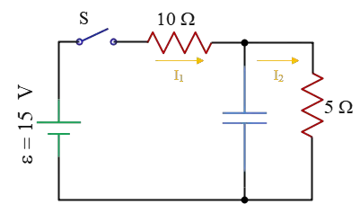
Solution: When a capacitor is placed (no matter in parallel or series) with a resistor in a circuit, just after closing the switch, it acts as a wire without any resistance.
Conversely, after passing a long time, it behaves like a resistor with infinite resistance.
Initially, the capacitor has no charge, so the potential difference across it, using the capacitance formula $\Delta V=\frac{Q}{C}$, is zero. On the other side, this capacitor is in parallel with the $5-{\rm \Omega}$ resistor.
Recall that when two electronic components (e.g., a capacitor or resistor) are in parallel, the potential drop across them is the same. According to this rule, the potential difference across the $5-{\rm \Omega}$ resistor is also zero. Applying Ohm's law, $\Delta V=IR$, we find that the current flowing through this resistor must also be zero.
Consequently, the current $I_2$ shown in the circuit, immediately after closing the switch, must be zero. In this situation, the $5-{\rm \Omega}$ resistor is removed and the circuit converts to the following
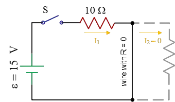
In this case, as you can see, $I_1$ shows the total current through the battery with $r=0$ whose value is determined by the following formula \[I=\frac{\mathcal{E}}{r+R_{eq}}=\frac{15}{0+10}=1.5\,{\rm A}\] Thus, just after closing the switch $S$, we have $I_1=1.5\,{\rm A}$ and $I_2=0$. The correct answer is b.
Note that in all AP Physics circuit multiple-choice problems, just after placing an initially uncharged capacitor in a circuit (like immediately after closing a switch in the circuit), it acts as a typical wire with zero resistance, and subsequently, all branches in parallel with it can be removed from the circuit.
Problem (14): In the circuit below, the capacitor is initially uncharged. A long time after closing the switch $S$, find the currents $I_1$ and $I_2$.
a. 1, 1 b. 1.5, 0 c. 0, 1.5 d. 1.5, 3
Solution: This is the same previous question, but now we want to analyze the circuit a long time later.
After a long time, when the switch is closed, the charge accumulation on the capacitor reaches its maximum value. At this moment, this charge, which is built on the plates of the capacitor, impedes completely the charge flowing by the battery (precisely, the current through this branch).
So, the current flowing through this branch is stopped and all total current delivered by the battery (i.e., $I_1$) reaching the junction $A$, flows into the branch where the $5-{\rm \Omega}$ resistor is presented. In other words, $I_1=I_2$.
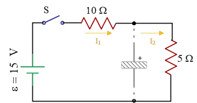
Thus, we can remove that branch including the capacitor, and find the total current through the circuit. In this case, the two $5-{\rm \Omega}$ and $10-{\rm \Omega}$ resistors are in series with an equivalent resistance of $R_{eq}=5+10=15\,{\rm \Omega}$.
On the other side, the current flowing through the circuit is found as \[I_t=\frac{\mathcal{E}}{r+R_{eq}}=\frac{15}{0+15}=1\,{\rm A}\] Therefore, \[I_1=I_2=I_t=1\,{\rm A}\] The correct answer is a.
In all AP Physics circuit multiple-choice questions, note that, after a long time of placing an initially uncharged capacitor in a circuit, it acts as an open circuit, and we can remove that branch from the circuit.
Author: Dr. Ali Nemati
Page Published: 10/13/2021
© 2015 All rights reserved. by Physexams.com
AP® is a trademark registered by the College Board, which is not affiliated with, and does not endorse, this website.