- Home
- Physics Problems
- Problems
Solved Problems
A gold wire of length 13.7 cm and diameter 0.188 mm is going to be used to construct a thermocouple. Gold has a temperature coefficient of resistivity of $\alpha =3.4\times {10}^{-3}{}^\circ {\rm C}^{-1}$.
(a) At $20{}^\circ {\rm C}$, gold has a resistivity of ${\rho }_{Au}=2.44\times {10}^{-8}\, \mathrm{\Omega }\mathrm{.m}$, what is the resistance of this wire at this temperature?
(b) After constructing out thermocouple, we place it into a liquid of unknown temperature and apply a voltage across the leads of the thermocouple of 0.224 V. If we measure a current of 0.884 A going through this thermocouple, what is the temperature of this liquid in $^\circ {\rm C}$?
Solution:
Note: the resistance of a conducting object with cross-sectional area $A$ an length $L$ is given by $R=\rho \ L/A$. So first calculate the $A$ of this wire as \begin{align*}A&=\pi r^2=\pi {\left(\frac{d}{2}\right)}^2\\&=\frac{\pi }{4}{\left(1.88\times {10}^{-4} \rm{m}\right)}^2\\&=2.78\times {10}^{-8} \quad {\rm m^2}\end{align*}
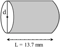
(a) Now we can calculate the resistance of the wire at $T=20{}^\circ {\rm C}$
\begin{align*}R_0&=\rho \frac{L}{A}\\ \\&=\left(2.44\times {10}^{-8}\right)\frac{\ 0.137}{2.78\times {10}^{-8}}\\ \\&=0.120\quad \rm{\Omega }\end{align*}
(b) By definition, the variation of the resistance with temperature is given by
\begin{align*}R&=R_0\left[1+\alpha \left(T-{T_0}\right)\right]\\ \\ &=R_0+\alpha R_0\left(T-T_0\right)\\ \\ \Rightarrow T&=T_0+\frac{R-R_0}{\alpha R}\\ \\&=20{}^\circ {\rm C}+\frac{\left(0.253-0.120\right)}{\left(3.40\times {10}^{-3}\right)\left(0.120\right)}\\ \\&=20{}^\circ {\rm C}+326{}^\circ {\rm C}\\ \\&=346{}^\circ {\rm C}\end{align*}
Problem (2): A cylindrical wire conductor of radius $\mathrm{a}$ as shown in the figure has a resistivity $\rho $ and carries a constant current.
(a) What is the magnitude and direction of the electric field vector $\vec{E}$ at the point just inside the wire at a distance a from the axis. Hint: recall that $\vec{J}=\sigma \vec{E}$ and that $I=JA$ where $A=\pi a^2$ is the cross-sectional area of the wire.
(b) What is the magnitude and direction of the magnetic field $\vec{B}$ just inside the wire at a distance $a$ from the axis?
(c) What is the magnitude and the direction of the Poynting vector $\vec{S}=\left(\frac{1}{{\mu }_0}\right)\left(\vec{E}\times \vec{B}\right)$ at this same point? The magnitude and direction of $\vec{S}$ is the rate and direction at which electromagnetic energy ($W/m^2$) is flowing into or out of the conductor.
(d) Recalling that $\vec{S}$ is the magnitude and direction of electromagnetic energy flow into or out of a conductor and use your part (c) answer to determine the rate of energy flow into the volume occupied by a length $l$ of the conducting wire. Hint: integrate $\vec{S}$ over the surface of this volume and compare your result to the rate of heat generation ($RI^2$ losses) in the same volume of wire.
Solution:
(a) The current density and electric field are related by $\vec{J}=\sigma \vec{E}$. Since in this case, $\vec{E}$ and $\vec{J}$ are parallel so \[E=\frac{J}{\sigma }=\rho J=\rho \frac{I}{\pi a^2}\] Where the resistivity $\rho $ is defined as the inverse of the conductivity $\sigma $. In above, we have used the definition of the current density as mention in the hint.
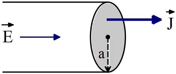
(b) Consider a circular loop of radius $r<a$ co-axis with the cylindrical wire. Ampere's law states that the line integral of the magnetic field around this loop is equals to the permeability times the total current passing through it. In the mathematical form is
\[\oint{\vec{B}.d\vec{l}}={\mu }_0I\]
Because $\vec{B}$ is tangent to the loop and of constant magnitude at every point on the loop, we have
\begin{align*} \oint{\vec{B}.d\vec{l}}&=B(2\pi a)\\&={\mu }_0I \\ \Rightarrow B&=\frac{{\mu }_0I}{2\pi a}\end{align*}
By using right hand rule- point your thumb of right hand in the direction of the current, the direction of the curling your fingers show the direction of the magnetic field- we can see that the magnetic field is tangent to the wire and perpendicular to the electric field.
(c) The energy flow of an electromagnetic field wave is represented by the Poynting vector $\vec{S}$, which is defined as
\[\vec{S}=\frac{1}{{\mu }_0}\vec{E}\times \vec{B}\]
Since $\vec{E}$ and $\vec{B}$ are perpendicular to each other - part (c)- so $S=\frac{1}{{\mu }_0}EB$
\begin{align*} S&=\frac{1}{{\mu }_0}\left(\frac{I}{\pi a^2}\right)\left(\frac{{\mu }_0I}{2\pi a}\right)\\&=\frac{{\mu }_0\rho I^2}{2{\pi }^2a^3{\mu }_0}\\&=\frac{\rho I^2}{2{\pi }^2a^3}\end{align*} At the top of the loop, the direction of the $E$ and $B$ are shown in the figure below. Using right hand rule, the direction of the $\vec{S}$ is into the page.
(d) \begin{align*} \int{SdA}&=\int{\frac{\rho I^2}{2{\pi }^2a^3}}\ 2\pi\,a\,dl\\&=\frac{\rho I^2}{2{\pi }^2a^3}.2\pi al\\&=\frac{\rho lI^2}{\pi a^2}\\&=\left(\rho \frac{l}{A}\right)I^2\\&=I^2R \end{align*}
The resistivity of gold is $2.44\times {10}^{-8}\mathrm{\Omega }\mathrm{.m}$ at room temperature. A gold wire that is $0.9\ \mathrm{mm}$ in diameter and $14\ \mathrm{cm}$ long carries a current of $940\ \mathrm{mA}$. What is the electric field in the wire?
Solution: The current density is defined as $J=I/A$, but this quantity is related to the electric field via $\vec{E}=\rho \vec{J}$ (this is an alternative version of Ohm's law for conducting objects!) thus we have $I=JA=\frac{1}{\rho }EA\Rightarrow E=\rho I/A$
\begin{align*} \Rightarrow E&=\rho \frac{I}{A_{disk}}\\&=\rho \frac{I}{\pi r^2}\\&=\left(2.44\times {10}^{-8}\right)\frac{940\times {10}^{-3}}{\pi {\left(\frac{0.9}{2}\times {10}^{-3}\right)}^2}\\&=0.0361\, {\rm \frac Vm} \end{align*}
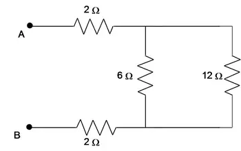
Problem (4): Thirteen resistors are connected across points A and B as shown in the figure. If all the resistors are accurate to 2 significant figures, what is the equivalent resistance between points A and B?

Solution: A far as possible, first simplify the diagram as below and then calculate the equivalence resistance.
The $6\, {\rm \Omega }$ and $12\, {\rm \Omega }$ are in parallel
\[\frac{1}{R_1}=\frac{1}{6}+\frac{1}{12}\Rightarrow R_1=4\,{\rm \Omega }\]
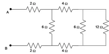
Three $4\, {\rm \Omega}$ resistors are in series so \[R_2=4+4+4=12\,{\rm \Omega }\]
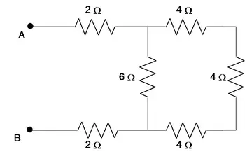
The $12\, {\rm \Omega }$ and $6\,{\rm \Omega }$ are in parallel so \[\frac{1}{R_3}=\frac{1}{12}+\frac{1}{6}\Rightarrow R_3=4\,{\rm \Omega }\]
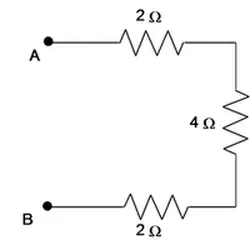
Therefore the equivalent resistance is $R_{eq}=2+4+2=8\,{\rm \Omega }$
The figure shows a $2.0\ \mathrm{cm}$ diameter roller that turns at $90\ \mathrm{rpm}$. A $4.0\ \mathrm{cm}$ wide plastic film is being wrapped onto the roller, and this plastic carries an excess electric charge having a uniform surface charge density of $5.0\ \mathrm{nC}/{\mathrm{cm}}^{\mathrm{2}}$. What is the current of the moving film?
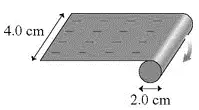
By definition of the electric current $I=Q/\Delta t\ $and surface charge density $\sigma =Q/A$, we must first find the area of the plastic film during $1\, \mathrm{s}$ moving and then multiply it by the $\sigma $ to calculate the total charge during this interval time. Thus,
\[\omega =90\ \mathrm{rpm} \xrightarrow{convert}\ 90\ \left(\frac{\mathrm{rev}}{\mathrm{min}}\right)\left(\frac{2\pi \mathrm{rad}}{\mathrm{1\ rev}}\right)\left(\frac{\mathrm{1\ min}}{\mathrm{60s}}\right)=9.425\frac{\mathrm{rad}}{\mathrm{s}}\]
The linear speed of the plastic film is determined by $v=\omega r=9.425\times 1=9.425\frac{\mathrm{cm}}{\mathrm{s}}$
The length has the plastic traveled during $1\,\mathrm{s}$ is $x=vt=9.425\ \mathrm{cm}$ so the area of it is $A=\left(9.425\times 4\right)=37.7\ {\rm cm^2}$. Now
\[Q=\sigma A=\left(5\times {10}^{-9}\frac{\mathrm{C}}{{\mathrm{c}\mathrm{m}}^{\mathrm{2}}}\right)\left(\mathrm{37.7\ }{\mathrm{cm}}^{\mathrm{2}}\right)\mathrm{=}188.5\mathrm{\ nC}\]
\[I=\frac{Q}{\Delta t}=\frac{188.5}{1}=188.5\ \mathrm{nA}\]
A $1\,\mu\mathrm{F}$ capacitor has a potential difference of $6.0\ \mathrm{V}$ applied across its plates. If the potential difference across its plates is increased to $8.0\ \mathrm{V}$, how much additional energy does the capacitor store?
Note: the energy stored in a capacitor is determined by the following equations:
\[U=\frac{1}{2}CV^2=\frac{Q^2}{2C}=\frac{1}{2}QV\] The given information is:
$C=1\,{\rm \mu F}$ and $V_1=6\, {\rm V}\ ,\ V_2=8\,{\rm V}$, therefore, \begin{gather*} U_1=\frac{1}{2}C_1V^2_1=\frac{1}{2}\left(1\right){\left(6\right)}^2=18\,{\rm \mu J} \\ \\ U_2=\frac{1}{2}C_2V^2_2=\frac{1}{2}\left(1\right){\left(8\right)}^2=32\,{\rm \mu J} \\ \\ \Rightarrow \Delta U=U_2-U_1=14\,{\rm \mu J}\end{gather*} Use each of them, where appropriate.
A parallel plate capacitor consists of two square plates of side length $10\, \rm cm$ that are spaced $5\,\rm mm$ apart with air between the plates. The plates are connected to a $200\,\rm V$ battery.
(a) Calculate the capacitance.
(b) Calculate the electric field between the plated.
(c) Calculate the amount of charge stored on each plate.
(d) Calculate the potential energy stored in the capacitor.
(e) An electron is released from the negative plane with a speed of $1.5\times {10}^7\,\mathrm{m/s}$ and accelerates towards the positive plate. What is the electron's speed when it strikes the positive plate?
(f) During this process, what is the electron's change in kinetic energy in electron volt?
(a) The capacitance of two parallel plates with area $A$ that is separated by $d$ is determine by $C=k{\epsilon }_0\frac{A}{d}$ where $k$ is the dielectric constant. Since there is air between the plates (without dielectric) so $k=1$ \begin{align*} C&={\epsilon }_0\frac{A}{d}\\\\&=(8.85\times {10}^{-12}) \frac{0.1\times 0.1}{0.005}\\ \\&=1.77\times {10}^{-11}\,\rm F \\ \\ &=17.7\,{\rm pF}\end{align*}
(b) Recall from section of the electric potential problems, the voltage or potential difference between two plates is given by $\Delta V=Ed$. Therefore \[E=\frac{\Delta V}{d}=\frac{200}{0.005}=4\times {10}^4\,{\rm N/C}\]
(c) By definition, the capacitance of a capacitor is $C=Q/V$, so \begin{align*}Q&=C\Delta V\\ \\&=(17.7\times {10}^{-12})(200)\\ \\&=35.4\times {10}^{-10}\quad {\rm C}\\ \\&=3.54\quad {\rm nC}\end{align*}
(d) By definition, the potential energy stored in a capacitor is $U=\frac{1}{2}CV^{2}=\frac{Q^2}{2C}=\frac{1}{2}QV$
\begin{align*}U&=\frac{1}{2}CV^2\\ \\&=\frac{1}{2}\left(17.7\times {10}^{-12}\right)(200)^{2}\\ \\&=35.4\times {10}^{-8}\,{\rm J}\\ \\&=354\quad{\rm nJ} \end{align*}
(e) Apply the kinetic-energy theorem $\Delta K=W_{net}$
Recall that because the charge of the electron is negative, the electric force $F_e=-eE$ acting on it is in the opposite direction of the electric field. So the angle between the force and displacement is $180^\circ$ and the physical work done on the electron is $W_e=F_ex\,{\cos 180^\circ}=-F_ex$. Therefore, we have \begin{gather*} K_2-K_1=W_{net}=W_e\\ \\ \frac{1}{2}mv^2_f-\frac{1}{2}mv^2_i=-\left(-eE\right)x=e\underbrace{Ex}_{\Delta V}\\ \\ \Rightarrow v_f=\sqrt{v^2_i+\frac{2e}{m}\mathrm{\Delta }V} \\ \\ =\sqrt{{\left(1.5\times {10}^7\right)}^2+\frac{2\left(1.6\times {10}^{-19}\right)}{9.11\times {10}^{-31}}(200)}\\ \\ =1.72\times {10}^7\quad {\rm m/s}\end{gather*}
(f) As above, we can write \begin{align*}\Delta K&=W_e=-(-eE)x\\ \\&=e\,\Delta V\\ \\&=e(200)\\ &=200\quad{\rm eV}\end{align*}
A nichrome wire is $50\ \mathrm{cm}$ long. The resistivity of the nichrome is $1.5\times {10}^{-6}\mathrm{\Omega }.\mathrm{m}$. The potential difference between the ends is $4.0\,\mathrm{V}$ and a current of $2.0\ \mathrm{A}$ is flowing through the wire.
(a) Calculate the resistance of the wire
(b) Calculate the diameter of the wire's circular cross section.
(c) Calculate the power dissipated in the wire.
(d) How many electrons per second pass through the cross section of the wire?
(a) Use Ohm's law to find the resistance of a conductor: $R=\frac{V}{I}=\frac{4}{2}=2\,\mathrm{\Omega }$
(b) The electrical resistance of a wire or conductor with resistivity $\rho $, length $L$ and area cross section $A$ is defined as $R=\rho \ L/A$. Thus,\begin{gather*} A=\pi {\left(\frac{d}{2}\right)}^2=\rho \frac{L}{R}\\ \\ \Rightarrow d=\sqrt{4\rho \frac{L}{R\pi }}\\ \\ =\sqrt{4\times \left(1.5\times {10}^{-6}\right)\frac{0.50}{2\pi }}\\ \\ =0.69\times {10}^{-3}\quad {\rm m}\\ \\ =0.69\quad {\rm mm}\end{gather*}
(c) Recall that the power dissipated in a resistor is defined by the following relations
\begin{gather*}P=VI=\frac{V^2}{R}=RI^2\\ \\ \Rightarrow P=VI=4\times 2=8\quad {\rm W}\end{gather*}
(d) Use the definitions of electric current, $I=\frac{\Delta }{q}{\Delta t}v$ ,and electric charge, $q=ne$, we have \begin{align*} I&=\frac{ne}{\Delta t}\\ \\ \Rightarrow n&=\frac{I\Delta t}{e}\\ \\&=\frac{2\times 1}{1.6\times {10}^{-19}}\\ \\&=1.25\times {10}^{19}\end{align*}
Two conductor made of the same material are connected across the same potential difference. Conductor A has twice the diameter and twice the length of conductor B. What is the ratio of the power delivered to A to the power delivered to B?
The power delivered to a conductor (resistor is a conductor) is given by: $P=\frac{V^2}{R}=VI=RI^2$ and the resistance of a cylindrical conductor is related to its resistivity $\rho $, length $l$ and cross-sectional area $A$ by$R=\rho \frac{l}{A}$. Therefore,
\[\frac{P_A}{P_B}=\frac{R_B}{R_A}=\frac{l_B}{l_A}\frac{A_A}{A_B}=\frac{1}{2}{\left(2\right)}^2=2\]
Where $A=\pi r^2$
A laser pulse that lasts $12\ \mathrm{ns}$ and delivers $255\,\mathrm{kW}$ of power to a spot size $0.15\mathrm{cm}$ on a target.
(a) What is the total energy delivered per pulse?
(b) If the wavelength of the laser $632\,\mathrm{nm}$, what is the frequency of the $EM$ wave?
(a) Given the power, we can calculate the energy delivered per pulse by the definition of the power as \begin{align*} P&=\frac{energy}{time}=\frac{U}{t} \\ \Rightarrow U&=Pt\\&=255\times {10}^3\times \left(12\times {10}^{-9}\right)\\ &=0.0031\quad \rm{J=3.1\,mJ\ per\ pulse}\end{align*}
(b) Frequency and wavelength are related to each other by
\[f=\frac{c}{\lambda }=\frac{3\times {10}^8}{632\times {10}^{-9}}=4.75\times {10}^{14}\mathrm{Hz}\]
A parallel-plate capacitor is constructed using two conducting plates of area $A$. They are placed at a separation of distance $d$ and initially there is vacuum between the plates. The capacitor is connected to a power source and is kept at a potential of $V$. A dielectric slab of area $A$ and thickness $d/2$ and dielectric constant $\kappa $ is inserted between the two plates.
(a) Calculate the charge on the plates before the slab is inserted.
(b) Calculate the charge on the plates after the slab is inserted.
(c) Calculate the work done in inserting the dielectric.
(a) Recall from the capacitance problems section that the capacitance of a parallel-plate capacitor is $C=\epsilon_0\kappa A/d$. So before the slab is inserted $C={\epsilon }_0A/d$ and $V=\frac{Q}{C}$ so, \[Q=V{\epsilon }_0A/d\]
(b) After insertion of the slab, one can show that there is two capacitor in series.
\begin{gather*} \frac{1}{C_{eq}}=\frac{1}{C_1}+\frac{1}{C_2}=\frac{1}{\frac{{\epsilon }_0A}{\frac{d}{2}}}+\frac{1}{\frac{\kappa {\epsilon }_0A}{\frac{d}{2}}} \\\\ \Rightarrow \frac{1}{C_{eq}}=\frac{d}{2{\epsilon }_0A}\left(1+\frac{1}{\kappa }\right) \\\\ \Rightarrow C_{eq}=\frac{2{\epsilon }_0A}{d}\left(\frac{\kappa }{\kappa +1}\right)\end{gather*} Now, use the definition of capacitance $C=\frac{Q}{V}$, and find the charge stored on its plates. \[\therefore Q'=C_{eq}V=\frac{2{\epsilon }_0A}{d}\left(\frac{\kappa }{\kappa +1}\right)V\]
(c) By definition, the work done on a system is equal to the change in the potential energy of that system. Therefore, we must calculate the difference in potential energy between two situations above:
\begin{align*} W&=U_{after}-U_{befor}\\\\ &=\frac{1}{2}C_{eq}V^2-\frac{1}{2}CV^2\\\\&=\frac{1}{2}V^2\left(\frac{{\epsilon }_0A}{d}\right)\left(\frac{2\kappa }{\kappa +1}-1\right) \end{align*} Thus, the work done on the system is obtained as \[W=\frac{V^2}{2}\left(\frac{{\epsilon }_0A}{d}\right)\frac{\kappa -1}{\kappa +1}\]
A dielectric slab of thickness $d$ and dielectric constant $K$ is inserted inside a capacitor with area $A$ and thickness $L$. A voltage difference $V$ is applied across the plats.
(a) Find the electric fields inside the air gap and inside the dielectric
(b) Find the surface charge density on each of the plates.
(c) Use the information in (b) to obtain the capacitance.
(d) Find the capacitance of the system using capacitors connected in series, and compare your result with part (c).

(a) Let $E_1$ be the electric field in the air and $E_2$ be in the dielectric.The electric 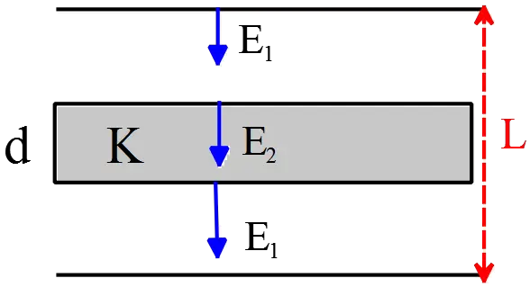 field in presence of a dielectric is $E_2=E_1/K\ $. If the electric field between two points to be uniform, then the potential difference between them is equal to the field strength $E$ multiplied by the points separation $L$ i.e.$\Delta V=EL$
Therefore, the potential difference between the plates are
\[\Delta V=E_1\left(L-d\right)+E_2d\]
Substituting $E_1/k$ for $E_2$, we obtain
\[\Delta V=\frac{E_1}{K}d+E_1\left(L-d\right)=E_1\left(\frac{d}{K}+\left(L-d\right)\right)\]
\[\therefore E_1=\frac{\mathrm{V}}{\left(\frac{d}{K}+\left(L-d\right)\right)}\]
\[E_2=\frac{E_1}{K}=\frac{V}{d+\left(L-d\right)}\]
(b) The electric field between two parallel conducting plates is $E=\sigma /{\epsilon }_0$, where $\sigma $ is the surface charge density of the plates. Therefore,
\[E_1=\frac{\sigma }{{\epsilon }_0}\to \sigma ={\epsilon }_0E_1={\epsilon }_0\frac{\mathrm{V}}{\left(\frac{d}{K}+\left(L-d\right)\right)}\]
(c) Given the charge density, we can find the amount of charge placed on the plates by $Q=\sigma A={\epsilon }_0\frac{\mathrm{V}}{\left(\frac{d}{K}+\left(L-d\right)\right)}A$. Now use the definition of the capacitance as $C=\frac{Q}{V}$ to find the capacitance of this capacitor.
\[C=\frac{Q}{V}={\epsilon }_0\frac{\mathrm{A}}{\left(\frac{d}{K}+\left(L-d\right)\right)}\]
(d) The above configuration can be illustrated as two parallel plate capacitors $C_1\ ,\ C_2$ that are in series. We know that the capacitance of such a capacitor is $C=\frac{k{\epsilon }_0A}{d}$ so
\[C_1=\frac{{\epsilon }_0A}{L-d}\ \ ,\ \ C_2=\frac{K{\epsilon }_0A}{d}\]
\[\frac{1}{C_{eq}}=\frac{1}{C_1}+\frac{1}{C_2}=\frac{1}{{\epsilon }_0A}\left(\frac{d}{K}+\left(L-d\right)\right)\]
\[C_{eq}=\frac{{\epsilon }_0A}{\frac{d}{K}+\left(L-d\right)}\]
A parallel plate capacitor with plates of area $A$ is filled with two dielectrics (of dielectric constants ${\kappa }_1$ and ${\kappa }_2$. Each dielectric slab has thickness $d/2$. Find the capacitance of the two arrangements in figures.

In figure a, the configuration of the dielectric slabs are like the series connected capacitors so recall that the equivalent capacitance of two capacitors that are connected in series is given by \begin{gather*} \frac{1}{C_{eq}}=\frac{1}{C_1}+\frac{1}{C_2}\\\\ \Rightarrow C_{eq}=\frac{C_1C_2}{C_1+C_2}\end{gather*}
Where $C_1={\kappa }_1{\epsilon }_0A/(\frac{d}{2})$ is the capacitance of the parallel plate capacitor. Therefore, \begin{align*}C_{eq}&=\frac{\left(\frac{{\kappa }_1{\epsilon }_0A}{\frac{d}{2}}\right)\left(\frac{{\kappa }_2{\epsilon }_0A}{\frac{d}{2}}\right)}{\left(\frac{{\kappa }_1{\epsilon }_0A}{\frac{d}{2}}\right)+\left(\frac{{\kappa }_2{\epsilon }_0A}{\frac{d}{2}}\right)}\\\\&=\frac{{\left(\frac{{\epsilon }_0A}{\frac{d}{2}}\right)}^2\left({\kappa }_1{\kappa }_2\right)}{\frac{2{\epsilon }_0A}{d}\left({\kappa }_1+{\kappa }_2\right)}\\\\&=\left(\frac{{\kappa }_1{\kappa }_2}{{\kappa }_1+{\kappa }_2}\right)\frac{2{\epsilon }_0A}{d}\end{align*}
In figure b, the slabs are connected in parallel so the equivalent capacitance of them is \begin{align*} C_{eq}&=C_1+C_2\\\\ &=\frac{{\kappa }_1{\epsilon }_0A}{\frac{d}{2}}+\frac{{\kappa }_2{\epsilon }_0A}{\frac{d}{2}}\\\\&=2\frac{{\epsilon }_0A}{d}({\kappa}_1+{\kappa}_2)\end{align*}
Four capacitors, each with a capacitance $10\,\mu\mathrm{F}$ are connected as shown in 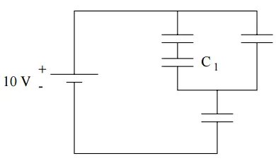 the figure to a $10\, \mathrm{V}$ battery. What is the charge on the capacitor $C_1$?
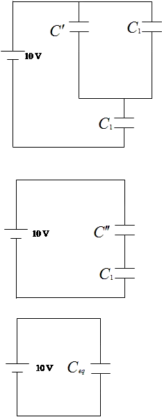
The two left capacitors in the upper branch are in series and have equivalent capacitance of $C^{'}=\frac{C_1C_1}{C_1+C_1}=\frac{C_1}{2}=5\,\mu\mathrm{F}$.
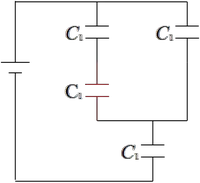
This is in parallel with the $10\,{\rm \mu F}$ in the facing branch so the equivalent capacitance of these two branch is $C^{''}=C^{'}+C_1=5+10=15\,{\rm \mu F}$. The equivalent capacitor of the top loop is in series with the lower capacitor $C_1$ and thus the total equivalent capacitance of the circuit is
\begin{align*} C_{eq}&=\frac{C^{''}C_1}{C^{''}+C_1}\\&=\frac{15\times 10}{15+10}\\&=6\quad {\rm \mu F}\end{align*} Recall that the capacitors in series have equal charges so the total charge of the circuit is \begin{align*} q_{tot}&=C_{eq}V=6\times 10=60\quad {\rm \mu C}\\ q_{tot}&=q_{C_1}=q_{C^{''}}=60\quad {\rm \mu C}\end{align*} The potential drop across the lower capacitor $C_1$ is $V_{C_1}=\frac{q_{C_1}}{C_1}=\frac{60}{10}=6\ \mathrm{V}$. we know that the sum of the potential drops across the capacitors in parallel is the total potential drop of the circuit, by using this fact, we find the potential drop across the upper network as follows \begin{align*} V&=V_{C_1}+V_{C^{''}}\\ \Rightarrow 10&=6+V_{C^{''}}\\\Rightarrow \ V_{C^{''}}&=4\ \mathrm{V}\end{align*} The upper network has two branches which are in parallel with each other so the potential drop across each of them is $4\, {\rm V}$. By knowing the voltage, we can find the charge stored in the left branch of the upper network as $q_{C^{'}}=C^{'}V_{C^{''}}=5\times 4=20\,\mu\mathrm{C}$. Therefore, the charge of the red capacitor is $20\,{\rm \mu C}$.
A cylindrical wire of radius $R$ carries a nonuniform current density $J(r)\ =\ ar$, where $r$ is the distance from the axis of the cylinder and $a$ is a constant. What is the total current $i$ which flows in the wire?
Using the definition of the current density $J$, we can compute the total current through the cross-sectional area of the wire
\[J=\frac{I}{A}\Rightarrow I=\int{\vec{J}.\hat{n}dA}\]
In this case, the current density is in the radial direction.
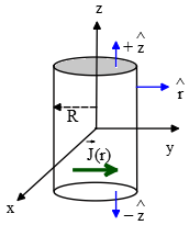
A cylindrical wire has three surfaces; top, bottom, and curved. The unit vector for the top and bottom is $\hat{n}=+\hat{z}\ ,\ -\hat{z}$, respectively and for the curved surface $\hat{n}=\hat{r}$. Therefore, the dot product of the top and bottom surfaces with $\vec{J}$ becomes zero.
\begin{align*}I_{tot}&=\int^R_0{\underbrace{ar\hat{r}}_{J(r)}\cdot\underbrace{\hat{r}}_{\hat{n}}\underbrace{(2\pi rdr)}_{dA}}\\ \\&=2\pi a\int^R_0{r^2dr}\\ \\&=\frac{2}{3}\pi aR^3\end{align*}
Consider the circuit shown at the right, where all resistors have the same resistance $R$. At $t=0$ with the capacitor $C$ uncharged, the switch is closed.
(a) At $t=0$ the three currents can be determined by analyzing a simpler, but equivalent, circuit. Identify this simpler circuit and use it to find the values of $I_1$, $I_2$ , and $I_3$ at $t=0$.
(b) At $t=\infty $, the currents can be determined by analyzing another equivalent circuit. Identify this simpler circuit and use it in finding the values of $I_1,\ I_2$ and $I_3$ at $t=\infty $.
(c) At $t=\infty $, what is the potential difference across the capacitor?
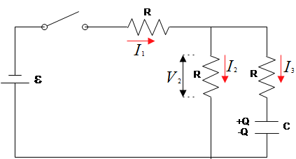
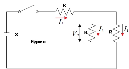
(a) At time $t=0$, since the capacitor is uncharged, it acts as a short circuit like a wire with no resistance so we can drop it out of the circuit (figure a) . In such a case, the two resistors in the left and middle branches are in parallel and their combinations with the third is in series. Thus,
\[R_{eq}=R+{\left(\frac{1}{R}+\frac{1}{R}\right)}^{-1}=\frac{3}{2}R\]
The main current in the circuit $I_1$ is found as
\[I_1=\frac{\mathcal{E}}{R_{eq}}=\frac{2\mathcal{E}}{3R}\]
The potential drop across the parallel resistors are the same $V_2=V_3$and the sum of the currents through them is equal to the total current in the circuit i.e. $I_1=I_2+I_3$. Recall that the sum of the potential drop across the series resistors is equal to the emf of the circuit i.e. $\mathcal{E}=V_1+V_{23}$, where $V_{23}$ is the voltage of the parallel branches. Using Ohm's law, we obtain \begin{align*} \mathcal{E}&=V_1+V_{23}\\ \\\to V_{23}&=\mathcal{E}-I_1R\\ \\&=\mathcal{E}-\frac{2\mathcal{E}}{3R}R\\ \\ \Rightarrow V_{23}&=\frac{1}{3}\mathcal{E}\end{align*}
We know $V_{23}=V_2=V_3$, therefore, \begin{gather*} I_2=\frac{V_2}{R}=\frac{\mathcal{E}}{3R} \\ \\ I_3=\frac{V_3}{R}=\frac{\mathcal{E}}{3R}\end{gather*}
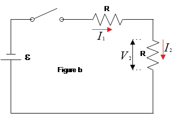
(b) At $t=\infty $, the capacitor is fully charged, so it acts like a wire with infinity resistance, using the Ohm's law, $I=V/R$, the current through it is zero i.e. $I_3=0$. In this case, indeed there is only two series resistors (see figure b).
\begin{gather*}R_{eq}=R+R=2R\\\ \\to I_{tot}=\frac{\mathcal{E}}{R_{eq}}=\frac{\mathcal{E}}{2R}\end{gather*}
Recall that in the series resistors, $I_{tot}=I_1=I_2$
(c) At $t=\infty $, there is no current in the branch containing the capacitor, so there is no potential drop across the resistor in this branch but, by definition of the capacitance $C=Q/V_C$, there must be potential difference across the capacitor. This branch and the middle branch are in parallel, so $V_2=V_C$. From part (a) we know that
\[V_2=V_{23}=\frac{1}{3}\mathcal{E}\]
Thus, $V_C=\mathcal{E}/3$.
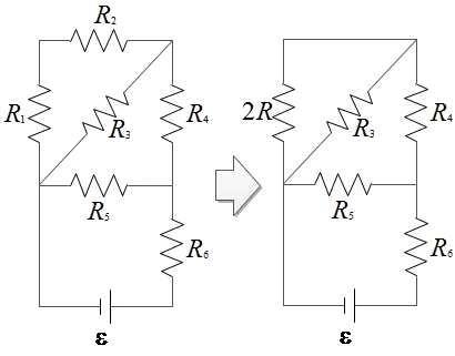
In the figure at the right assume $R=1.2\, {\rm \Omega}$. What is the 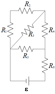 equivalent resistance of the circuit connected to the battery?
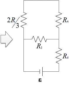
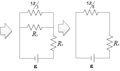
The resistors $R_1$ and $R_2$ are in series which we call their combinations as $R_{12}=R_1+R_2=2R$. The $R_{12}$ and $R_3$ are in parallel, so their combination is \begin{align*} \frac{1}{R_{123}}&=\frac{1}{R_{12}}+\frac{1}{R_3}\\ \to R_{123}&=\frac{R_{12}R_3}{R_{12}+R_3}\\&=\frac{R^2}{3R}=\frac{R}{3}\end{align*} $R_{123}$ and $R_4$ are in series \begin{align*}R_{1234}&=R_{123}+R_4\\&=\frac{2}{3}R+R\\&=\frac{5}{3}R\end{align*} $R_{1234}$ and $R_5$ are in parallel \begin{align*} R_{12345}&=\frac{R_{1234}R_5}{R_{1234}+R_5}\\&=\frac{\frac{5}{3}R\times R}{\frac{5}{3}R+R}\\&=\frac{5}{8}R\end{align*} $R_{12345}$ and $R_6$ are in series, thus the equivalent resistor of the circuit is \[R_{eq}=\frac{5}{8}R+R=\frac{13}{8}R\]
(a) A dielectric capacitor with a capacitance of $C_0=20\,\mu{\rm F}$ is charged up to $V_0=60\, {\rm V}$. What is the energy $U_0$ stored in the capacitor?
(b) The capacitor is then disconnected from everything else. The dielectric is removed, changing the capacitance to $C_1=10\,\mu {\rm F}$. What was the dielectric constant $\kappa$ of the dielectric?
(c) The capacitor is still disconnected. What are the new charge $Q_1$, voltage $V_1$, and energy $U_1$ stored in the capacitor?
(d) Did the energy of the capacitor increase or decrease? Where did the energy come from/go to?
(a) The energy stored in a capacitor is found by $U=\frac{1}{2}CV^2=\frac{1}{2}QV=Q^2/2C$. Since $C$ and $V$ has given, we can choose \begin{align*}U_0&=\frac{1}{2}C_0V^2_0\\ \\ &=\frac{1}{2}(20 {\rm \mu {F}}){\left(\mathrm{60V}\right)}^{2}\\ \\&=36000\quad {\rm \mu J}\\ \\&=36\quad mJ\end{align*}
(b) With dielectric $\kappa $, the capacitance of capacitors becomes $\kappa $ times the case without the dielectric that is
\[\kappa =\frac{C_{with}}{C_{without}}=\frac{20}{10}=2\]
(c) After disconnecting from battery, since there is no source to build up the charges so the total amount of charges on the plates of capacitors must be constant. By definition of capacitance, we have \begin{align*} Q_0&=C_0V_0\\&=(20\,\rm{ \mu F})(60)\\&=1200\quad {\rm \mu C}=Q_1 \\ \\ V_1&=\frac{Q_1}{C_1}\\ &=\frac{1200}{10}\\&=120\quad {\rm V}\\ \\ U_1&=\frac{1}{2}C_1V^2_1\\&=\frac{1}{2}(10)(120)^{2}\\&=72\quad {\rm mJ}\end{align*}
(d) Without explicit calculation we could expect the energy stored in the capacitor must be increase since removing dielectric requires some work does on the capacitor. This work deposited into the energy of the capacitor.
The capacitance of a cylindrical capacitor can be increased by:
(a) decreasing both the radius of the inner cylinder and the length
(b) increasing both the radius of the inner cylinder and the length
(c) increasing the radius of the outer cylindrical shell and decreasing the length
(d) decreasing the radius of the inner cylinder and increasing the radius of the outer cylindrical shell
(e) only by decreasing the length
The capacitance of a cylindrical capacitor, comprising of a long cylindrical conductor with
radius $r_a$ and linear charge density $+\lambda $, and a coaxial cylindrical conducting shell with radius $r_b$ , $r_b>r_a$, and linear charge density $-\lambda $ is calculated as
\[C=\frac{2\pi {\epsilon }_0L}{{\mathrm{ln} r_b\ }-{\mathrm{ln} r_a\ }}=\frac{2\pi {\epsilon }_0L}{{\mathrm{ln} \left(\frac{r_b}{r_a}\right)\ }}\]
Where $L$ is the length of the cylinder. As you can see, the capacitance is inversely proportional to the difference of logarithm of the inner and outer cylinder. Therefore by increasing the inner radius $r_a$, its logarithms is also increasing. As a result, difference between the two logarithms is decreasing and consequently the capacitance of the system is increased.
The correct answer is B.
A $20\,{\rm \mu F}$ capacitor is charged to $200\,{\rm V}$. its stored energy is:
(a) $4000\ \mathrm{J}$
(b) $4\ \mathrm{J}$
(c) $0.4\ \mathrm{J}$
(d) $0.1\ \mathrm{J}$
(e) $0.004\ \mathrm{J}$
The stored energy in a capacitor with any shape is found with one of the following formulas
\[U=\frac{1}{2}CV^2=\frac{Q^2}{2C}=\frac{1}{2}QV\]
Where $C$ is the capacitance of the capacitor and $Q$ is the total charge loaded on its planes. So \begin{align*} U&=\frac{1}{2}CV^2\\ &=\frac{1}{2}\left(20\times {10}^{-6}\right){(200)}^2\\&=0.4\quad {\rm J}\end{align*}
The correct answer is C.
Which of the following graphs best represents the current-voltage relationship for a device that obeys Ohm's law?
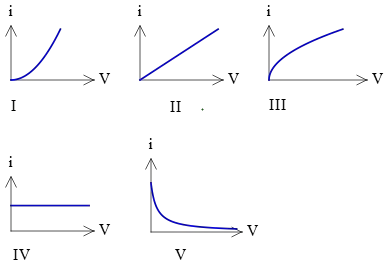
In the section of Ohm's law questions, we were familiarized with the ohmic materials. The resistance in such materials is defined as the ratio of the potential difference across a conductor to the current in the conductor \[R=\frac{\Delta V}{I}\] That is resistance is the slope of the $V-I$ graph. Based upon experimental evidence, ohmic materials have a linear current-potential difference relationship over a broad range of applied potential differences. Therefore,
The correct answer is B.
MOST USEFUL FORMULA IN CAPACITANCE AND RESISTANCE:
Capacitor: any pair of conductors separated by an insulating material.
\[C=\frac Q V\]
The SI unit of capacitance is Farad
\[\mathrm {1\,F=1\, C/V}\]
$Q$ is the conductor's total charge and $V$ is the potential drop across the capacitor.
Capacitance of a parallel plate capacitor in vacuum:
\[C=\epsilon_0 \frac A D\]
Capacitance of a spherical capacitor:
\[C=4\pi\epsilon_0 \frac{r_ar_b}{r_b-r_a}\]
where $r_b$ and $r_a$ are the outer and inner radii,respectively.
Capacitance of a spherical capacitor:
\[C=\frac{2\pi\epsilon_0L}{\ln\left(\frac {r_b}{r_a}\right)}\]
where $r_b$ and $r_a$ are the outer and inner radii,respectively.
Capacitors in Series:
\[\frac 1{C_{eq}}=\frac 1{C_1}+\frac 1{C_2}+\frac 1{C_3}+\cdots\]
In a series connection the magnitude of charge on all plates is the same.
Capacitors in parallel:
\[C_{eq}=C_1+C_2+C_3+\cdots\]
In a parallel connection the potential drop across each capacitor is the same.
Potential energy stored in a capacitor:
\[U=\frac{Q^{2}}{2C}=\frac 1 2 CV^2=\frac 1 2 QV\]
Electric energy density in a vacuum:
\[u=\frac 1 2 \epsilon_0 E^2\]
Definition of current:
\[I=\frac{dQ}{dt}\]
Definition of current density:
\[J=\frac I A\]
Definition of resistivity:
\[\rho=\frac E J\]
Resistance of a conductor:
\[R=\rho \frac L A\]
The SI unit of resistance is ohm ($\Omega$).
Ohm's law:
\[I=\frac V R\]
© 2015 All rights reserved. by Physexams.com
AP® is a trademark registered by the College Board, which is not affiliated with, and does not endorse, this website.
