Solved Problems
The circuit shown in the figure has reached equilibrium (steady-state) and the power output of the $2\Omega $ resistor is $8\ {\rm W}$. The switch is closed, and the circuit is once again given enough time to come to equilibrium. Find the change in the charge on each capacitor from the initial equilibrium state to the final equilibrium state.
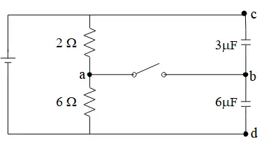
With having the power of $2\Omega $ resistor, we can find the current through it as below
\[P=RI^2_{2\Omega }\Rightarrow I_{2\Omega }=\sqrt{\frac{8}{2}}=2\ {\rm A}\]
Before closing the switch: The resistors are in series so $R_{eq}=2+4=6\ \Omega $ and ${\mathcal E}=R_{eq}I$ or ${\mathcal E}=Q_{tot}/C_{eq}$ so
\[{\mathcal E}=R_{eq}I=6\times 2=12\ {\rm V}\] And the capacitors are in series so $C_{eq}=\frac{6\times 3}{6+3}=2\ \mu {\rm F}$. Recall that all capacitors in series have the same charge i.e. $Q_3=Q_6=Q_{tot}$
\[\Rightarrow Q_{tot}=C_{eq}{\mathcal E}{\rm =2\times 12=24\ }\mu {\rm C} \]
After closing the switch: since there are no components between $a$ and $b$, so the $V_a=V_b$. The point $c$ and $d$ are directly connected to the positive and negative terminals of the battery, respectively so $V_c=12{\rm \ V}$ and $V_d=0$.
In steady state, we only have current through resistors so again the current in the circuit is $I=2{\rm \ A}$. Apply the loop rule to the $adc$ to find the $V_a$ as \begin{gather*} V_a+2I=V_c \\ \Rightarrow V_a=12-2\left(2\right)=8\quad {\rm V} \\ \therefore V_a=V_b=8\ {\rm V}\end{gather*}
Now with knowing $V_a,V_b$ and $V_c$, we can find the potential drop across the capacitors and subsequently the charges.\begin{align*}{Q'_3}&=C_3\left|V_{bc}\right|\\&=C_3\left|V_c-V_b\right|\\&=3\times (12-8)\\&=12\quad{\rm \mu C} \\\\ {Q'_6}&=C_6\left|V_{bd}\right|\\&=C_6\left|V_b-V_d\right|\\&=6\times (8-0)\\&=48\quad {\rm V}\end{align*} Therefore, we get \begin{align*} \Delta Q_3&={Q'_3}-Q_3\\&=12-24\\&=-12\quad {\rm \mu C} \\\\ Q_6&={Q'_6}-Q_6\\&=48-24\\&=24\quad {\rm \mu C}\end{align*}
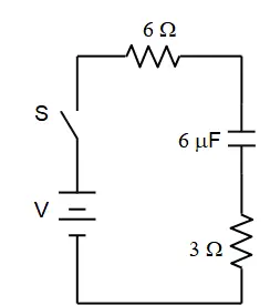
In the following circuit, the capacitors are initially uncharged. At $t=0$, the switch is closed. Find the following at $10\ {\rm ms}$. (${\mathcal E}=12{\rm V}$)
(a) The charge on each capacitor
(b) The current through each resistor
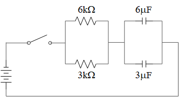
(a) First after closing the switch, find the equivalent resistance and capacitance to be able to determine the time constant of the circuit i.e. $\tau=RC$.
The two resistors and capacitors are in parallel so $C_{eq}=6+3=9\ \mu {\rm F}$ and $R_{eq}=\frac{6\times 3}{6+3}=2\ {\rm k}\Omega $ thus $\tau=R_{eq}C_{eq}=2\times 9=18\ {\rm ms}$
We know that in charging mode the charge on the capacitor at any moment of time is given by $Q\left(t\right)=C{\mathcal E}\left(1-e^{-\frac{t}{\tau}}\right)$. Therefore, the total charge on the capacitors after $t=10\ {\rm ms}$ is $Q\left(10\ {\rm ms}\right)=C_{eq}{\mathcal E}\left(1-e^{-\frac{t}{\tau}}\right)=\left(9\times 12\right)\left(1-e^{-\frac{10}{18}}\right)=46\ \mu {\rm C}$
Now with the given $Q$, we can find the potential difference $\Delta V_{ab}$ across the capacitors
\[\Delta V_{ab}=\frac{Q_{10\ {\rm ms}}}{C_{eq}}=\frac{46}{9}=5.115\ {\rm V}\]
All components in parallel have the same potential drop i.e. $\Delta V_{6\mu F}=\Delta V_{3\mu F}$
\[\Rightarrow Q_6=C_6\Delta V_6=6\times 5.115=30.7\ \mu {\rm C}\]
\[Q_3=C_3\Delta V_3=3\times 5.115=15.3\ \mu {\rm C}\]
(b) In charging mode the current through the circuit is given by $I\left(t\right)=\frac{{\mathcal E}}{R_{eq}}{\exp \left(-\frac{t}{\tau}\right)\ }$. Therefore, $I\left(t=10\ {\rm ms}\right){\rm =}\frac{{\rm 12}}{{\rm 2000}}{\exp \left(-\frac{10}{18}\right)\ }=3.44\ {\rm mA}$. The potential drop across the equivalent resistance is $\Delta V_{ac}=R_{eq}I\left(t\right)=2000\times 0.00344=6.88\ {\rm V}$. we have $\Delta V_{6k}=\Delta V_{3k}=6.88\ {\rm V}$ therefore
\[I_{6k}=\frac{\Delta V_6}{R_6}=\frac{6.88}{6000}=1.148\ {\rm mA}\]
\[I_{3k}=\frac{\Delta V_3}{R_3}=\frac{6.88}{3000}=2.245\ {\rm mA}\]
The following circuit is in its steady-state; the charge on the $6\,\mu {\rm F}$ capacitor is $90\,\mu{\rm C}$. Find the
(a) value of the EMF and
(b) the charge on the $3\,\mu {\rm F}$ capacitor.
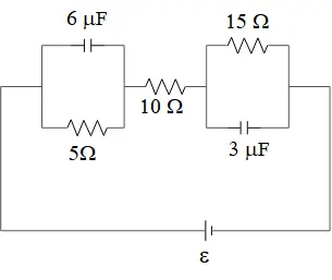
Steady state means that the current does not increase or decrease and the capacitors in the circuit are fully charged. Recall that in any branch of a circuit with fully charged capacitor current is zero!
(a) First, find the potential drop across the capacitor $6\mu{\rm F}$ via $\Delta V_{6\mu F}=\frac{Q}{C}=\frac{90}{6}=15\ {\rm V}$. Since the $5\Omega $ resistor and $6\,\mu{\rm F}$ capacitor are in parallel so the potential drop across them is equal:
\[I_{5\Omega }=\frac{\Delta V}{R}=\frac{15}{5}=3\,{\rm A}\]
Now ignore the capacitors in the circuit and use the hint that in series circuits all components have the same current, find the unknown EMF as
\[I_{5\Omega }=I_{{\rm 10}\Omega }=I_{15\Omega }=I_{tot}\Rightarrow {\mathcal E}=I_{tot}R_{eq}\]
But the three resistors are in series and $R_{eq}=5+15+10=30\Omega $, therefore,
\[{\mathcal E}=3\times 30=90\ {\rm V}\]
(b) Given the $I_{15\Omega }$, we can find the potential drop across the $3\mu {\rm F}$ capacitor and subsequently via $Q_{3\mu F}=C\Delta V_{3\mu F}$
\[\Delta V_{3\mu F}=I_{15\Omega }R=3\times 15=45{\rm V}\]
\[\therefore Q_{3\mu F}=C\Delta V_{3\mu F}=3\times 45=135\mu {\rm C}\]
In the circuit shown, point ``a'' is at $-20\ {\rm V}$ with respect to ground. Find the value of the unknown EMF, the value of the unknown resistor, the magnitude and direction of the current through the $5\,\Omega $ resistor.
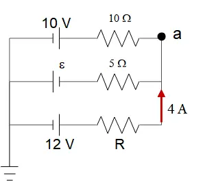
As shown in the figure, the points $a,d,e$ are equipotential with $V=-20\ {\rm V}$ and points $b,c,f$ are equipotential with $V=0$.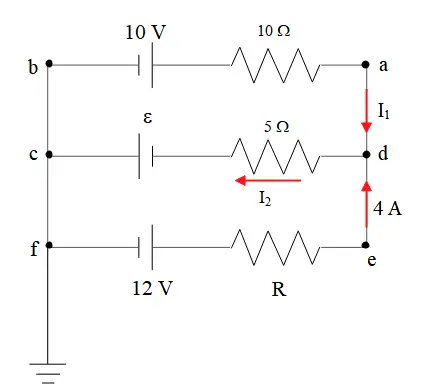
Apply the Kirchhoff's loop rule to the branch $ab$ to find the current passing the $10\Omega $:
\[V_b-10-I_110=V_a\Rightarrow 0+10-10I_1=-20\]
\[\Rightarrow I_1=3\ {\rm A}\]
Since the current is positive, so the direction of the chosen initial arbitrary current $I_1$ is correct.
Apply the junction rule to find the $I_2$ as
\[I_1+4=I_2\Rightarrow I_2=3+4=+7{\rm A}\]
Now apply loop rule to the $cd$: $V_d-5I_2+{\mathcal E}=V_c\Rightarrow -20-5\left(7\right)+{\mathcal E}=0\Rightarrow {\mathcal E}=55\ {\rm V}$
To find the unknown resistor $R$, now apply the loop rule to the branch $fe$
\[V_f+12-4R=V_e\Rightarrow 0+12-4R=-20\Rightarrow R=8\ \Omega \]
Therefore, the direction of the current through $5\ \Omega $ is from $d$ to $c$.
In the following circuit, the capacitor is initially uncharged. At $t=0$, the switch is thrown to position ``a''. When the voltage across the capacitor reaches $10\ {\rm V}$, the switch is automatically and simultaneously thrown to ``b''. Find the following quantities at $t=100\ {\rm ms}$,
(a) The charge on the capacitor
(b) The magnitude and direction of the current through each capacitor.
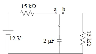
(a) When the switch sits on $a$, the capacitor begins to charge. Recall that in such a circuit (RC), the charge on the capacitor in charging mode is given by
\[Q\left(t\right)=C{\mathcal E}\left(1-{\exp \left(-\frac{t}{RC}\right)\ }\right)\]
Where $Q_f=C{\mathcal E}$ is the final charge on the capacitor. At time $t$ we have $V=10{\rm V}$ and $Q(t)=C\Delta V=2\left(10\right)=20\ \mu{\rm C}$ therefore
\[Q\left(t\right)=C{\mathcal E}\left(1-{\exp \left(-\frac{t}{RC}\right)\ }\right)\Rightarrow 20=2\left(12\right)\left(1-{\exp \left(-\frac{t}{30}\right)\ }\right)\]
\[\Rightarrow \ {\exp \left(-\frac{t}{30}\right)\ }=1-\frac{10}{12}\Rightarrow t=53.75\ {\rm ms}\]
Where $\tau=RC=\left(15{\rm k}\Omega \right)\left({\rm 2}\mu {\rm F}\right){\rm =30\ ms}$ is the time constant.
At $t=53.75\ {\rm ms}$ the switch closes and the capacitor is discharging with initial charge $Q_0=20\mu {\rm C}$. But we know that in discharging mode the charge on the capacitor is given by $Q(t^{'})=Q_0{\exp \left(-\frac{t^{'}}{RC}\right)\ }$. So $RC=\left(40{\rm k}\Omega \right)\left({\rm 2}\mu {\rm F}\right)=80\ {\rm ms}$ and $t^{'}=100-53.75\ {\rm s}$ after starting the discharging mode, the charge on the capacitor is
\[Q\left(100-53.75\right)=20{\exp \left(-\frac{100-53.75}{80}\right)\ }\Rightarrow \ Q=11.2\ \mu{\rm C}\]
(b) The currents at discharging and charging mode in the $RC$ circuits are given by
\[{\rm Charging}:I\left(t\right)=\frac{{\mathcal E}}{R}e^{-\frac{t}{RC}}\]
\[{\rm Discharging:}I\left(t\right)=\frac{V_0}{R}e^{-\frac{t}{RC}}\ {\rm or}\ \frac{Q_o}{RC}e^{-\frac{t}{RC}}\ \]
After $t=100-53.75\ {\rm ms}$ the resistor $40\ {\rm k}$ is in a circuit with discharging capacitor so $I_{40k}=\frac{Q_0}{RC}e^{-\frac{t}{RC}}=\frac{20\times {10}^{-6}}{30\times {10}^{-3}}{\exp (-\frac{46.25}{80})\ }=0.00014\ {\rm A}$ but no current passing through the resistor $15\ {\rm k}\Omega $ i.e. $I_{15k}=0$!
In the steady state circuit shown below, ($i$) the power output of the $4\,\Omega $ resistor is $324\ {\rm W}$; ($ii$) the voltage drop across the $10\ \Omega $ resistor is $50\ {\rm V}$; and ($iii$) point ``b'' is at a higher potential than point (a). Find:
(a) The value of the unknown EMF
(b) The magnitude of the unknown resistor
(c) The magnitude and direction of the current through it; and
(d) The charge on the capacitor. Which plate is positively charged?
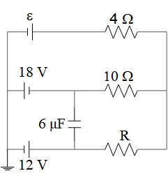
From ($i$) we can find the current through the resistor $4\Omega $ as
\[P=RI^2\Rightarrow 324=4I^2\Rightarrow I=9\Omega \]
From ($ii$) find the current through the $10\Omega $ as $I_1=\frac{V}{R}=\frac{50}{10}=5\ {\rm A}$
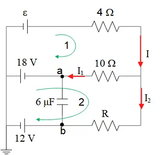
(a) Now use the Kirchhoff's loop rule in clockwise direction in the loop $1$ to determine the unknown EMF as \begin{gather*} +{\mathcal E}-4I-10I_1+18=0 \\\\ \Rightarrow \quad +{\mathcal E}-4(9)-10(5)+18=0\\\\ \Rightarrow \quad {\mathcal E}=+68\quad {\rm V}\end{gather*}
(b) Apply the Kirchhoff's loop rule in the loop $2$ as shown in the figure.
\begin{gather*} -18+10I_1-RI_2-12=0\\\\ \Rightarrow \quad -18+10(5)-R(4)-12=0\\\\ \Rightarrow\quad R=5\quad \Omega \end{gather*}Note: we have to use the junction rule as $I=I_1+I_2$ to find the $I_2$.
(c) Because the initially chosen direction has yield the correct sign for all of the currents in the circuit, so the current passing through the $R$ is from right to left.
(d) First find the potential drop across the capacitor via the loop rule between point $a$ and $b$, then use the definition of the capacitor $Q=C\Delta V$ to determine its charge.
\begin{gather*} V_a+I_1\left(10\right)-I_2R=V_b\\\\ \Rightarrow \quad V_b-V_a=10(5)-4(5)=30\quad {\rm V} \\\\ Q=30(6)=180\quad {\rm \mu F}\end{gather*}
Since $V_b>V_a$ so the bottom plate is positive
Note: the current passing through a fully charged capacitor is zero!
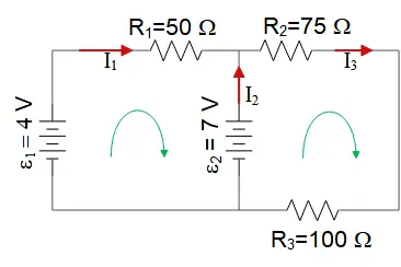
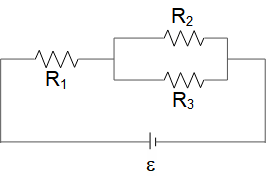
What is the current through resistor $R_1$ in this circuit?
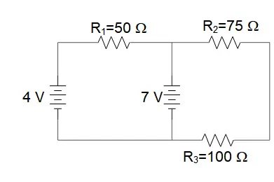
Apply Kirchhoff's junction and loop rules. First, modify the picture as below
Junction rule: $I_1+I_2=I_3$
Loop rule for left panel: $-I_3R_2-I_3R_3+{{\mathcal E}}_2=0$
\[\Rightarrow I_3=\frac{{{\mathcal E}}_2}{R_2+R_3}=\frac{7}{75+100}=0.07\ {\rm A}\]
Loop rule for right panel: $-I_1R_1-{{\mathcal E}}_2+{{\mathcal E}}_1=0$
\[\Rightarrow I_1=\frac{{{\mathcal E}}_1-{{\mathcal E}}_2}{R_1}=\frac{4-7}{50}=-0.06\ {\rm A}\]
From the junction rule we can find the $I_1$as
\[I_2=I_3-I_1=0.07-\left(-0.06\right)=0.13\ {\rm A}\]
The minus sign indicates that the initially chosen direction of $I_1$ is wrong! so $I_1$ must be counter clockwise.
A multiloop circuit is shown in the figure. Some circuit quantities are not labeled. It is not necessary to solve the entire circuit. What is the current $I_2$?
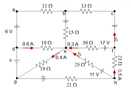
Apply Kirchhoff's rules to the right below triangle i.e. ${\rm efh}$ in the clockwise direction by starting from the point "h" as below \begin{gather*} -11-25I_2+0.3(30)-17+(23)(0.5)=0\\\\ \Rightarrow \quad 25I_2=-7.5 \\\\ \Rightarrow \quad I_2=-0.3\quad {\rm A}\end{gather*} The minus sign indicates that the direction of the $I_2$ have been chosen initially wrong i.e. it must be counterclockwise.
For the circuit shown in the figure, the switch S is initially open and the capacitor voltage is $80\ {\rm V}$. The switch is then closed at time $t=0$. How long after closing the switch will the current in the resistor be $7.0\ \mu {\rm A}$?
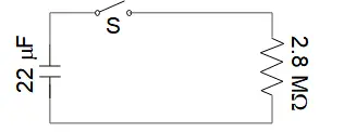
Recall that the current in the $RC$ circuits after closing or opening the switch S is given by $I\left(t\right)=I_0{\exp \left(-\frac{t}{RC}\right)\ }$, where $I_0$ is the initial current at $t=0$. The voltage across the resistor is the same as the capacitance so $I_0=\frac{V_0}{R}=\frac{80}{2.8\times {10}^6}=2.857\times {10}^{-5}\ {\rm A}$. Therefore, by definition of the time constant $\tau$ in the $R-C$ circuits, we have
\[\tau=RC=\left(2.8\times {10}^6\right)\left(22\times {10}^{-6}\right)=61.6\ {\rm s}\]
\[I\left(t\right)=I_0{\exp \left(-\frac{t}{RC}\right)\ }\Rightarrow \ 7\mu {\rm A}=\left(25.87\mu {\rm A}\right){\exp \left(-\frac{t}{61.6}\right)\ }\]
Taking natural logarithm on both sides gives
\[{\ln \left(\frac{7}{25.87}\right)\ }=-\frac{t}{61.6}\Rightarrow t=86.6\ {\rm s}\]
For the circuit shown in the figure, $I=0.5\ {\rm A}$ and $R=12\ \Omega $. What is the value of the emf ${\mathcal E}$?
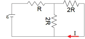
The two resistors $2R$ are in parallel so $\frac{1}{R_{2,2}}=\frac{1}{2R}+\frac{1}{2R}=\frac{2}{2R}\Rightarrow R_{2,2}=R$. Now the $R_{2,2}$ is in series with the $R$, so $R_{eq}=R_{2,2}+R=2R=2\left(12\right)=24\ \Omega $.
Given the $I$ in the figure, we can calculate the voltage of $2R$ resistor in the right branch \[V_{2R}=I\left(2R\right)=\left(0.5\right)\left(2\times 12\right)=12\ {\rm V}\]
The voltages in the parallel circuits are the same so using Ohm's law find the current in the other $2R$ as $I^{'}=\frac{V}{2R}=\frac{12}{2\left(12\right)}=0.5\ {\rm A}$.
The currents in the parallel must be sum so $I_{tot}=I+I^{'}=0.5+0.5=1\ {\rm A}$.
This current is the total current in the circuit since the two 2R resistors are in series with R and we know that the current through any component in a series circuit is the same.
Now multiply the total current by the equivalent resistance of the circuit to find the emf:
\[{\mathcal E}=I_{tot}R_{eq}=(1)(24)=24\quad {\rm V}\]
The capacitor circuit in the figure has an $18.0\ {\rm V}$ battery connected to the capacitors with the following capacitance: $C_1=24.6\ \mu {\rm F}$ , $C_2=14.2\ \mu{\rm F}$ , $C_3=36.2\ \mu{\rm F}$.
(a) Find the equivalence capacitance of this circuit.
(b) Find the charge on each capacitor.
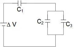
(a) The $C_2$ and $C_3$ are in parallel so they have the same voltage and the sum of their currents are equal to the total current of the circuit. With these notes we have
\[C_{23}=C_2+C_3=14.2+36.2=50.4\ \mu{\rm F}\]
The capacitors $C_{23}$ and $C_1$ are in series so the equivalence of the circuit is
\[\frac{1}{C_{eq}}=\frac{1}{C_1}+\frac{1}{C_{23}}=\frac{1}{24.6}+\frac{1}{50.4}=0.06049\Rightarrow C_{eq}=16.5\ \mu{\rm F}\]
(b) Use the definition of the capacitor to find the total charge of the circuit i.e. $Q_{tot}=C_{eq}\Delta V=16.5\times 18=298\ \mu {\rm C}$. All capacitors in series have the same charge so $Q_{tot}=Q_1=Q_{23}=298\,\mu {\rm C}$. Therefore
\[C_1=\frac{Q_1}{\Delta V_1}\Rightarrow \ \Delta V_1=\frac{Q_1}{C_1}=\frac{298}{24.6}=12.11\ {\rm V}\]
\[\Delta V_{23}=\frac{Q_{23}}{C_{23}}=\frac{298}{50.4}=5.91\ {\rm V}\]
As noted in part (a), all capacitors in parallel have the same voltage difference so
\[\Delta V_{23}=\Delta V_2=\Delta V_3=5.91\ {\rm V}\]
\[{{\rm Q}}_{{\rm 2}}{\rm =}{{\rm C}}_{{\rm 2}}\Delta V_2=14.2\times 5.91=83.8\ \mu {\rm C}\]
\[Q_3=C_3\Delta V_3=36.2\times 5.91=214\ \mu {\rm C}\]
A capacitor of capacitance $C=4\ \mu {\rm F}$ has been charged so that the potential difference between its plates is 80\, {\rm V}. The capacitor is then connected to a $25\, {\rm k\Omega} $ resistor as shown. The switch S is closed and the capacitor begins to discharge
(a) Calculate the time constant of the circuit
(b) Determine the charge on the capacitor when the switch is closed at $t=0$
(c) Calculate the current through the resistor immediately after the switch is closed
(d) Calculate the current $10\ {\rm ms}$ after the switch is closed.
(e) Calculate the time after which the potential difference has decreased to one-half its maximum value.
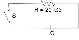
(a) By definition, the quantity $RC$ which appears in the RC circuit problems, is called the time constant. So for this circuit $RC=\left(25\times {10}^3\right)\left(4\times {10}^{-6}\right)=0.1\ {\rm s}$
(b) The initial charge is related to the capacitance and voltage via
\[Q_0=CV_0=\left(4\ {\rm F}\right)\left(80\ {\rm V}\right)=320\ \mu {\rm C}\]
(c) The initial current is related to the voltage and resistance via
\[I_0=\frac{V_0}{R}=\frac{80}{25\times {10}^3}=3.2\times {10}^{-3}A=3.2\ {\rm mA}\]
(d) To find the current at any moment in time, we must analyze the $RC$ circuits in the discharging mode as follows:
Use Kirchhoff's loop law to write an equation for the circuit.
\[\frac{q}{C}-IR=0\Rightarrow \frac{q}{C}-R(-\frac{dq}{dt})=0\Rightarrow -\frac{dt}{RC}=\frac{dq}{q}\]
\[\Rightarrow {\ln q\ }=-\frac{t}{RC}+Const.\ \Rightarrow q\left(t\right)=q_0\,e^{-\frac{t}{RC}}\]
The current in the circuit at any moment is by definition
\[I\left(t\right)=-\frac{d}{dt}q\left(t\right)=\frac{q_0}{RC}e^{-\frac{t}{RC}}=I_0e^{-\frac{t}{RC}}\]
Since the charge is decreasing, so we must add a minus sign to compensate it. We can check the result obtained in part c with the equation above.
\[I\left(t=10\times {10}^{-3}{\rm s}\right){\rm =}\left({\rm 3.2\ mA}\right){\exp \left(-\frac{10\times {10}^{-3}}{0.1}\right)\ }=2.89\ {\rm mA}\]
(e) We can use the definition of capacitance or Ohm's law to find the instantaneous voltage via
\[V\left(t\right)=\frac{q\left(t\right)}{C}=\frac{q_0}{C}e^{-\frac{t}{RC}}=V_0e^{-\frac{t}{RC}}\ \ \ {\rm or}\ \ \ \ V\left(t\right)=I\left(t\right)R=RI_0e^{-\frac{t}{RC}}=V_0e^{-\frac{t}{RC}}\]
We want to find the time at which $V\left(t\right)=\frac{1}{2}V_0$, so
\[\frac{1}{2}V_0=V_0e^{-\frac{t}{RC}}\ \ \Rightarrow \frac{1}{2}=e^{-\frac{t}{RC}}\]
By taking natural logarithm from both sides of the above equation, we obtain
\[{\ln 2\ }=\frac{t}{RC}\Rightarrow t=RC\ {\ln 2\ }=0.1\ {\ln 2\ }=0.069\ {\rm s}\]
For the resistor circuit shown,$R_1=1\,\Omega\,R_2=R_3=R_4=6\,\Omega\,R_4=6\,\Omega $. The battery provides a potential difference of $V_0=12\,{\rm V}$.
(a) Find the equivalent resistance.
(b) Calculate the potential drop across each of the resistors and the current through each resistor.
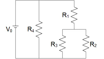
(a) The $R_2$ and $R_3$ are in parallel, so $\frac{1}{R_{23}}=\frac{1}{R_2}+\frac{1}{R_3}=\frac{1}{4}+\frac{1}{4}=\frac{1}{2}\Rightarrow R_{23}=2\,\Omega $.
$R_{23}$ and $R_1$ are in series so $R_{23,1}=R_{23}+R_1=2+1=3\,\Omega $
$R_{23,1}$ and $R_4$ are in parallel so $\frac{1}{R_{eq}}=\frac{1}{R_{23,1}}+\frac{1}{R_4}=\frac{1}{3}+\frac{1}{6}=\frac{1}{2}\Rightarrow R_{eq}=2\,\Omega $
(b) First find the total current by $I_{tot}=\frac{V_0}{R_{eq}}=\frac{12}{2}=6\,{\rm A}$. Resistors in parallel all have the same potential drop, so
\[V_{23,1}=V_4=V_0=12\ {\rm V}\]
\[I_{23,1}=\frac{V_{23,1}}{R_{23,1}}=\frac{12}{3}=4\ {\rm A\ ,\ \ }I_4=\frac{{V}_{4}}{{R}_{4}}=\frac{12}{6}=2\ {\rm A}\]
The sum of the $I_{23,1}$ and $I_4$ must be total current in the circuit $I_{tot}$.
Resistors in series all have the same current, so
\[I_{23,1}=I_{23}=I_1=4\ {\rm A}\]
\[V_1=I_1R_1=4\times 1=4\ {\rm V\ \ ,\ \ } V_{23}=I_{23}R_{23}=4\times 2=8\ {\rm V}\]
The sum of the $V_1$ and $V_{23}$ must be the total differential potential circuit (since these are in parallel to the battery). To find the current through $R_2$ and $R_3$, since these are in parallel to each other so all have the same differential drop i.e. $V_2=V_3=8V$
\[I_2=\frac{V_2}{R_2}=\frac{8}{4}=2{\rm A\ ,\ \ }I_3=\frac{V_3}{R_3}=\frac{8}{4}=2{\rm A}\]
To check that we are on the right way, the sum of the $I_2$ and $I_3$ must be equal to $I_1$ because they are in series!
In summary: $I_1=4{\rm A\ ,\ } I_2=I_3=I_4={\rm 2A\ ,\ }{{\rm V}}_{{\rm 1}}{\rm =4V,\ \ }{{\rm V}}_{{\rm 2}}{\rm =}{{\rm V}}_{{\rm 3}}{\rm =8V\ ,\ }{{\rm V}}_{{\rm 4}}{\rm =12V}$
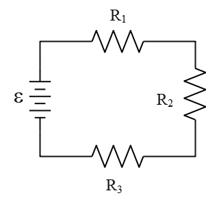
Calculate the current $I_2$ through and the voltage $\Delta V_2$ across the second resistor $R_2$ in the diagram. The other quantities are $R_1=5\,\Omega $,$R_2=4\,\Omega $ , $R_3=3\,\Omega $ , ${\mathcal E}=9\,{\rm V}$
First, calculate the total current of the diagram. $R_2$ and $R_3$ are in parallel and their combination with $R_1$ are in series. So
\[\frac{1}{R_{23}}=\frac{1}{R_2}+\frac{1}{R_3}=\frac{1}{4}+\frac{1}{3}=\frac{7}{12}\Rightarrow R_{23}=\frac{12}{7}\Omega \]
\[R_{eq}=R_1+R_{23}=5+\frac{12}{7}=6.71\Omega \]
Using Ohm's law $I_{tot}=\frac{{\mathcal E}}{R_{er}}=\frac{9}{6.71}=1.34\,{\rm A}$.
Recall that the current through each resistors that are in series are the same, so $I_1=I_{23}=I_{tot}$. $R_2$ and $R_3$ are in parallel thus the potential across them is equal. From the notes above, we have
\[I_1=1.34{\rm A}\]
\[V_{23}=I_{23}R_{23}=1.34\times 1.71=2.29\,{\rm V}\]
\[I_2=\frac{V_{23}}{R_2}=\frac{2.29}{4}=0.57\,{\rm A}\]
\[I_3=\frac{V_{23}}{R_3}=\frac{2.29}{3}=0.76\,{\rm A}\]
The potential difference across $R_1$ is also $V_1=I_1R_1=1.34\times 5=6.7\,{\rm V}$
In the circuit shown, $R=150\,\Omega $ , $R_1=R_2=10\,\Omega $ , ${{\mathcal E}}_1=12\,{\rm V}\ $and ${{\mathcal E}}_2=9\,{\rm V}$. First, write down three equations that can be solved for the three currents. Then find that the current through resistor $R$.
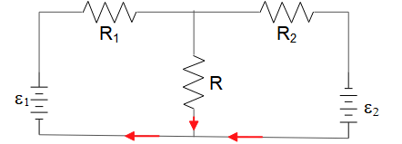
Apply Kirchhoff's junction and loop rules to find the basic equations of the circuit.
\begin{gather*} {\rm Junc:}I_1=I+I_2\quad ,\quad (1)\\ {\rm left\ loop:}\ +{{\mathcal E}}_1-I_1R_1-IR=0 (2)\quad,\quad \\ {\rm right\ loop:}\ {{\mathcal E}}_2+IR-I_2R_2=0\quad ,\quad (3)\end{gather*}
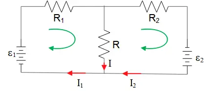
Solve for $I_1$ and $I_2$ then substitute them into (1)
\[\begin{cases}\left(2\right)&\Rightarrow I_1=\displaystyle{\frac{{{\mathcal E}}_1-IR}{R_1}}\\\left(3\right)&\Rightarrow I_2=\displaystyle{\frac{{{\mathcal E}}_2+IR}{R_2}} \end{cases}\] We know that $I_1=I+I_2$, therefore,
\[\frac{{{\mathcal E}}_1-IR}{R_1}=I+\frac{{{\mathcal E}}_2+IR}{R_2}\]
If we rearrange the above expression, we get \begin{gather*} \left(\frac{{{\mathcal E}}_1}{R_1}-\frac{{{\mathcal E}}_2}{R_2}\right)=I\left(1+\frac{R}{R_2}+\frac{R}{R_1}\right)\\\\ \Rightarrow \left(\frac{12}{10}-\frac{9}{10}\right)=I\left(1+\frac{150}{10}+\frac{150}{10}\right)\\\\ \Rightarrow I=\frac{0.3}{31}=9.67\times {10}^{-3}\ {\rm A=9.67\ mA}\end{gather*}
Now substitute $I_1$ into $I_2$ and $I_3$, then \begin{align*} I_1&=\frac{{{\mathcal E}}_1-IR}{R_1}\\\\&=\frac{12-(9.67\times {10}^{-3})(150)}{10}\\\\&=1.054\quad {\rm A}\\\\I_2&=\frac{{{\mathcal E}}_2+IR}{R_2}\\\\&=1.045\ {\rm A}\end{align*}
In the circuit shown in Figure, switch S is closed at time $t=0$
(a) Find the reading of each meter just after S is closed.
(b) What does each meter read long after S is closed?
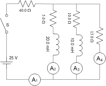
(a) Recall that the current in an RL circuit with ${\mathcal E}$ (emf) is given by $i=\frac{{\mathcal E}}{R}\left(1-e^{\left(-\frac{R}{L}\right)t}\right)$. Now just after $S$ is closed, currents in $R-L$ branches is $i\left(t=0\right)=0$ so $A_2=A_3=0$ subsequently, the above circuit looks like two resistors are connected in series.
\[R_{eq}=R_1+R_2=40+15=55\ \Omega \]
\[\therefore i_1=i_4=\frac{V}{R_{eq}}=\frac{25}{55}=0.455\ {\rm A}\]
Another reasoning: At the very instant that S is closed, inductors are maximally resisting. So they essentially PREVENT current flow through the $5\,\Omega $ and $10\,\Omega $ resistor!
(b) Long after closing the switch, the inductors act like a regular wire. So we add the $5,10,15\Omega $ resistors in parallel to get
\[\frac{1}{R_{eq}}=\frac{1}{R_5}+\frac{1}{R_{10}}+\frac{1}{R_{15}}=\frac{1}{5}+\frac{1}{10}+\frac{1}{15}\to R_{eq}=2.72\ \Omega \]
\[I_{total}=\frac{V}{R_{tot}}=\frac{25}{2.7+40}=0.585\ {\rm A}\]
Therefore, $A_1=0.585\ {\rm A}$.
The $5\,\Omega {\rm ,10}\,\Omega {\rm ,15}\,\Omega $ parallel resistors all have the same potential drop, so \[V_5=V_{10}=V_{15}=R_{eq}i_{tot}=2.72\times 0.585=1.57\ {\rm V}\]
Given the voltage across each resistors, one can determine the current through each of then \[A_2=\frac{1.57}{5}=0.314\,{\rm A\qquad}A_3=\frac{{\rm 1.57}}{{\rm 10}}{\rm =0.157\,A\qquad}A_4=\frac{1.57}{15}=0.104\,{\rm A}\]
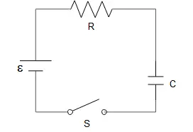
An emf source with potential difference ${\mathcal E}$ and internal resistance $r$ is connected to a resistor $R$ and a capacitor with capacitance $C$ in series connection through a switch $S$ as in the figure. Initially, there is no charge in the capacitor and at $t=0$ switch $S$ is closed. Write your answers in terms of ${\mathcal E},r, R, C$.
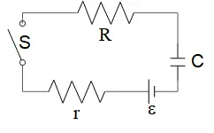
(a) Show the direction of the positive current flow and write down the equation for a charge on the capacitor for $t>0$, using Kirchhoff's rules. (note that your equation should include the charge $q$, only (not current) as a dependent variable)
(b) Show that $q\left(t\right)=C{\mathcal E}\left(1-e^{-\frac{t}{\tau}}\right)$, is the solution for the equation you write in part (a) by directly substituting it into equation provided that $t$ is chosen properly. Determine $t$
(c) What is the initial current at $t=0$ when the switch $S$ is closed? What is the current passing through the circuit at $t>0$?
(d) What is the maximum amount of charge that can be stored in the capacitor and when is this amount of charge accumulated in the capacitor?
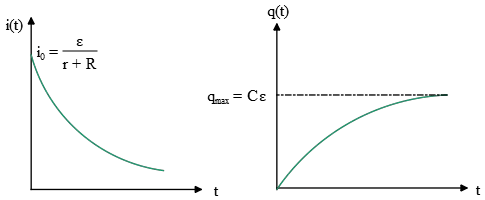
(e) Plot current versus time and charge versus time graphs. Show the initial and final current/charge values in the graphs.
(f) How much energy is stored in the capacitor at some time $t_1>0$?
(g) How much heat (energy) has been generated in the resistor $R$ from $t=0$ to $t=t_1$?
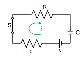
(a) By convention, the positive current flowing in a circuit is from the positive terminal toward the negative terminal. Therefore, the current is clockwise. Apply Kirchhoff's loop rule to find the charge equation of the circuit:
\[{\mathcal E}-ir-iR-\frac{q}{C}=0\ \ {\rm set}\ i=\frac{dq}{dt}\]
\[\Rightarrow \ {\mathcal E}-\left(r+R\right)\frac{dq}{dt}-\frac{q}{C}=0\]
(b) We can solve the above equation directly, or substitute the solution in the equation and check its correctness as follows:
\[\left. \begin{array}{rcl}
q\left(t\right) & = & C{\mathcal E}\left(1-e^{-\frac{t}{\tau}}\right) \\
\displaystyle{\frac{dq}{dt} & = & \frac{C{\mathcal E}}{t}e^{-\frac{t}{\tau}}}
\end{array}
\right\}\ {\mathcal E}-\left(r+R\right)\frac{C{\mathcal E}}{t}e^{-t/\tau}-{\mathcal E}\left(1-e^{-t/\tau}\right)=0\]
So $q(t)$ is a solution if $\frac{\left(r+R\right)C}{t}=1\to \ t=\left(r+R\right)C$
(c) This setup illustrates the charging mode of a capacitance. We know that in this case the current of the circuit is given by $i\left(t\right)=\frac{{\mathcal E}}{R}{\exp \left(-\frac{t}{RC}\right)\ }=i_0\,{\exp \left(-\frac{t}{RC}\right)\ }$ where $i_0$ is the initial current. Therefore, at $t=0\to q\left(0\right)=0\ $then from (a) ${\mathcal E}-i_0\left(r+R\right)=0\to i_0=\frac{{\mathcal E}}{r+R}$ or $i_0=\frac{C{\mathcal E}}{t}$. Thus, the current through the circuit at any time $t>0$ is
\[i\left(t\right)=\frac{{\mathcal E}}{R+r}{\exp \left(-\frac{t}{RC}\right)\ }\]
(d) At the instant that the switch is closed, the capacitance has no charge and so $q_{ini}(t=0)=0$ but after a long time it charges. That is $q_{max}=q\left(t\to \infty \right)=C{\mathcal E}$ since
\[q\left(t\right)=\mathop{{\rm lim}}_{t\to \infty }C{\mathcal E}\left(1-e^{-\frac{t}{\tau}}\right)\to C{\mathcal E}\]
(e)
(f) The energy stored in a capacitor is given by one of the following relations
\[U=\frac{1}{2}CV^2=\frac{Q^2}{2C}=\frac{1}{2}QV\]
Now, in this case, we can use the middle relation:
\[U_C\left(t_1\right)=\frac{q^2\left(t_1\right)}{2C}=\frac{1}{2}C{{\mathcal E}}^2{\left(1-e^{-\frac{t_1}{\tau}}\right)}^2 where t=\left(r+R\right)C \]
(g) Power dissipation in resistor $R$ equals to $P\left(t\right)=R\,i^2\left(t\right)=i^2_0Re^{-\frac{2t}{\left(R+r\right)C}}$
Energy dissipated from $t=0$ to $t=t_1$: $W=\int^{t_1}_0{P\left(t\right)dt}=i^2_0R\int^{t_1}_0{e^{-\frac{2t}{\left(R+r\right)C}}dt}$
\[\therefore W=i^2_0\frac{R\left(R+r\right)}{2}\left(1-e^{-\frac{2t_1}{\left(R+r\right)C}}\right)\ ,\ where\ i_0=\frac{{\mathcal E}}{r+R}\]
(a) The switch $S$ is closed at time $t=0$. Find the time constant of this circuit. Explain your reasoning.
(b) Suppose the switch $S$ is closed for a long time and the equilibrium is reached. Then, all of a sudden, if the switch $S$ is reopened at time $t=0$, find the power dissipated through the resistor $R$ as a function of time.
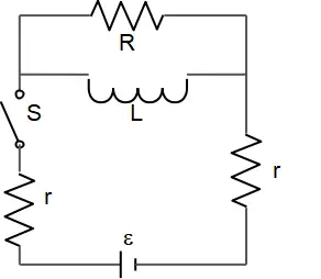
(a) In the $R-L$ circuit, the quantity $\tau=L/R\ $is called the time constant. This is a measure of how quickly the current reaches its final value. For example, at a time equal to $\tau$, the current has risen to about $63\%$ of its final value, or in a time equal to $2\tau$, the current reaches $86\%\ $of its final value.
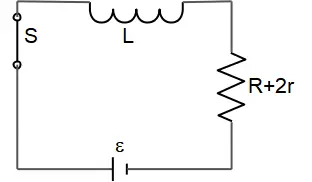
After closing switch $S$, the current flows in the circuit. The resistors are in series so the equivalent resistor is $R_{eq}=R+r+r=R+2r$ and the circuit reduces to the following figure.
Therefore, the time constant of this circuit is
\[\tau=\frac{L}{R_{eq}}=\frac{L}{R+2r}\]
(b) When the switch is closed for a long time, the inductor acts like a short circuit, that is, the inductor acts like a wire with zero resistance, so the potential drop across $R$ is zero.
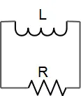
In this case, the current through the circuit is found, by Ohm's law, as $i=V/2r$. Immediately after the switch $S$ is opened, the current in the main branch of the circuit is zero, but in the inductor changes continuously. Applying the loop rule to the circuit below gives the current in the inductor and $R$ as time.
\[-IR-L\frac{dI}{dt}=0\Rightarrow \frac{dI}{I}=-\frac{R}{L}dt\]
Integrating and solving for $I$ gives
\[I(t)=I_0\,{\exp \left(-\frac{R}{L}t\right)\ }\]
This is the rate of change of the current after the switch $S$ is opened. $I_0$ is the current just before the switch is opened which in this case is $I_0=V/2r$. Recall that the power dissipated in the resister $R$ is $P_{diss}=RI^2(t)$. So
\[P_{diss}\left(t\right)=R{\left(\frac{V}{2r}\right)}^2{\exp \left(-\frac{R}{L}\right)\ }\]
Consider the $LC$ circuit shown in the figure. If the charge on the left plate of the capacitor is known to be $q=-Q_{max}/2$ and decreasing at time $t=0$, find expressions for the charge on the left plate and current as a function of time. Here, $Q_{max}$ is the maximum charge the capacitor can have in such a circuit.
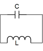
The $LC$ circuit has a characteristic property that the charge and current through it oscillate in sharp contrast to the exponential approach in the $RL$ and $RC$ circuits. To see this property, let us consider the right plate of the capacitor has an initial positive charge $Q_0$. Since at $t=0$, the capacitor has half of the maximum charge and decreasing with time that is the magnitude of the negative charge increases so the circuit is in the charging mode. By choosing positive direction for $I$ as counter clockwise and applying Kirchhoff's loop rule to the circuit, which says that all the potential differences around a closed loop must sum to zero, we obtain
\[\Delta V_C+\Delta V_L=0\Rightarrow -\frac{Q}{C}+\left(-L\frac{dI}{dt}\right)=0\]
Recall that the potential difference in the direction of the current is $\Delta V_c=-Q/C$ for capacitor and across the inductor is $-L\ dI/dt$. By the definition of the current we have
\[I=\frac{dQ}{dt}\]
By substituting this into the equation above, we obtain
\[\frac{Q}{C}+L\frac{d^2Q}{dt^2}=0\]
This is the equation of charge on the capacitor at each instant that has exactly the same forms as the equation of simple harmonic motion. Therefore, its solution is
\[Q\left(t\right)=Q_0{\cos (\omega t+\alpha)\ }\ ,\ \ \omega=\frac{Q}{LC}\]
The charge on the right plate of the capacitor oscillates back and forth between $-Q_0$ and $Q_0$ with period $T=2\pi/\omega$.
In this problem, the equation of charge of the circuit is $Q\left(t\right)=Q_{max}{\cos(\omega t+\alpha)\ }$ and at time $t=0$, $Q\left(t=0\right)=-Q_{max}/2$, with these information, find the phase constant of the circuit as
\[-\frac{Q_{max}}{2}=Q_{max}\,{\cos \left(\omega \left(0\right)+\alpha\right)\ }\Rightarrow \ {\cos \alpha\ }=-\frac{1}{2}\Rightarrow \alpha=\pm \frac{2\pi}{3}\]
Since the capacitor is in charging mode, so we must choose the phase constant $\alpha=+2\pi/3$ to match the condition.
Consider the $LC\ $circuit shown in the figure.
(a) If the current $i=I_{max}/2$ is known to flow in the clockwise direction and the charge on the left plate is known to be positive at time $t=0$
(b) If the current $i=I_{max}/2$ is known to flow in the clockwise direction and the charge on the left plate is known to be positive at time $t=T/2$, where $T$ is the period of an $LC$ circuit
Find expressions for the current and charge on the right plate of the capacitor as a function of time. Here, $I_{max}$ is the maximum current in such a circuit.
(a) In the $LC$ circuit, as the charge oscillate, so does the current through the inductor. Using the equation $I=dQ/dt$ and the capacity charge $Q=Q_m{\cos (\omega t+\alpha)\ }$, we get
\begin{align*} I(t)&=\frac{dQ}{dt}\\&=-Q_0\, \omega \,{\sin \left(\omega t+\alpha\right)\ }\\&=-I_0\, {\sin \left(\omega t+\alpha\right)\ }\end{align*} At time $t=0$, $I\left(t=0\right)=I_{max}/2$, with these given, we can find the phase constant of the circuit
\begin{align*} I\left(t=0\right)&=\frac{I_{max}}{2}\\&=-I_{max}\,{\sin \left(\omega \left(0\right)+\alpha\right)\ }\\ \Rightarrow {\sin \alpha\ }&=-\frac{1}{2} \\ \Rightarrow \alpha&=\frac{5\pi}{6}\end{align*}
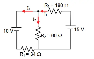
What is the current through resistor $R_3$ in this circuit?
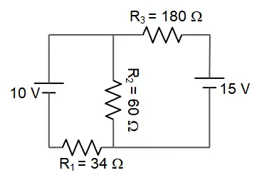
First, we must choose a positive direction for each branch of the circuit as shown in the figure. The junction rule gives $I_1=I_2+I_3$. Applying Kirchhoff's loop rule to the left and right loop in the circuit separately gives
\begin{gather*} right:\ +15-I_1R_3-I_2R_2=0\\ left:\ -10-I_3R_1+I_2R_2=0\end{gather*}
We have three unknowns and three equations, so substitute the $I_1$ into the above equations and solve for the $I_2$ and $I_3$.
\[\left\{ \begin{array}{c} +15-\left(I_2+I_3\right)R_3-I_2R_2=0 \\ -10-I_3R_1+I_2R_2=0 \end{array} =\left\{ \begin{array}{rcl}-I_3R_3-I_2\left(R_2+R_3\right)+15 & = &0 \\ -I_3R_1+I_2R_2-10 & = &0 \end{array}\right.\right.\]
\[=\left\{ \begin{array}{rcl}-180I_3-240I_2+15 & = & 0 \\ -34I_3+60I_2-10 & = & 0 \end{array} \right.\]
the results for the equations above can be combined to solve for $I_3$. To do this, first multiply the first equation by $60$ and the second equation by $240$ then add these equations to eliminate $I_2$ and solve for $I_3$:
\[\left(\left(-180\times 60\right)-\left(240\times 34\right)\right)I_3+\left(15\times 60-240\times 10\right)=0\]
\[\Rightarrow I_3=-0.0791\ {\rm A}\]
Substitute $I_3$ in the equation for the left loop to solve for $I_2$:
\[-10-I_3R_1+I_2R_2=0\to \ -10-34\left(-0.0791\right)+I_2(60)=0\Rightarrow I_2=0.1218\ {\rm A}\]
Now substitute $I_2$ and $I_3$ in the junction rule to solve for $I_1$
\[I_1=I_2+I_3=0.1218+\left(-0.0791\right)=+0.0427\ {\rm A}\]
Note: for analyzing circuits, the positive directions of the currents do not matter. Assign a positive direction for each branch and solve for each of the currents. If this initially chosen current is correct then the associated current will get positive, otherwise, we will get a negative value for the current. In this case, the negative sign is the only an indication of choosing the wrong direction! So the correct direction of the $I_3$ is opposite to the initially assigned direction.
How long does it take after the switch S is closed for the energy stored in the capacitor in the RC circuit below to reach $75\%\ $of its maximum value?
In an RC circuit problem, after closing switch $S$, using Kirchhoff's loop rule we can find the charge stored at the plates of the capacitor at any time as follows
\[+{\mathcal E}-\frac{Q}{C}-IR=0\to {\mathcal E}=R\frac{dQ}{dt}+\frac{Q}{C}\]
We have used the current definition as the time rate of the charge $I=dQ/dt$. Rearranging above, we can get an equation for the charge on the capacitor
\[\frac{dQ}{dt}+\frac{1}{RC}Q-\frac{{\mathcal E}}{R}=0\]
Its solution is $Q\left(t\right)=\underbrace{{\mathcal E}C}_{Q_f}\left(1-{\exp \left(-\frac{t}{\tau}\right)\ }\right)$, where $\tau=RC$ is called the time constant of the RC circuit and $Q_f$ is the final charge of the capacitor. We know that the energy stored in a capacitor at any time in the charging and discharging cases, is found by the following relation
\begin{align*} U_C&=\frac{Q^2\left(t\right)}{2C}\\\\ &=\frac{1}{2C}{\left({\mathcal E}C\right)}^2{\left(1-{\exp \left(-\frac{t}{\tau}\right)\ }\right)}^2\\\\&=\underbrace{\frac{1}{2}C{{\mathcal E}}^2}_{U_{C,max}}{\left(1-{\exp \left(-\frac{t}{\tau}\right)\ }\right)}^2\end{align*} Setting $U_C\left(t=?\right)=0.75\,U_{C,max}$, we obtain \begin{gather*} 0.75\,U_{C,max}=U_{C,max}{\left(1-{\exp \left(-\frac{t}{\tau}\right)\ }\right)}^2\\\\ \Rightarrow 1-{\exp \left(-\frac{t}{\tau}\right)\ }=\sqrt{0.75}\end{gather*}
\[\Rightarrow \ {\exp \left(-\frac{t}{\tau}\right)\ }=0.134\ \]
Taking the natural logarithm of the both sides, we get
\[-\frac{t}{\tau}={\ln \left(0.134\right)\ }\Rightarrow t=2.01\ RC\]
In the diagram $R_1>R_2>R_3$. Rank the three resistors according to the current in them, least to greatest.
(a) 1,2,3
(b) 3,2,1
(c) 1,3,2
(d) 3,1,2
(e) All are the same.
All electric components of such a circuit is in series. Recall that in series circuits the electric current passing through all components is the same. Therefore, the correct answer is E.
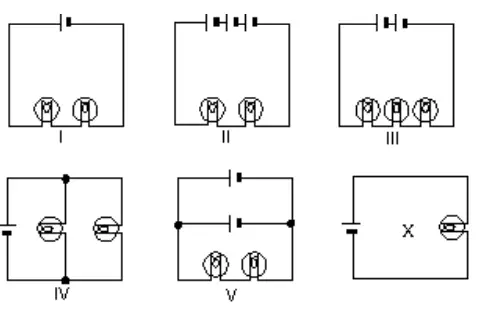
In the diagrams, all light bulbs are identical and all emf devices are identical. In which circuit (I, II, III, IV, V) will the bulbs glow with the same brightness as in the circuit X?
(a) I
(b) II
(c) III
(d) IV
(e) V
The brightness of a light bulb is determined by the current passing through it so we must find the current through each bulb in each of the above circuits.
Using Ohm's law, $I=V/R$, and series and parallel considerations, we have
In (I) the two bulbs are in series so $R_{eq}=2R$ and $I_{tot}=V/2R$. Recall that current in the series circuits is the same for all components so $i_1=i_2=V/2R$.
In(II) we have two bulbs and sources so $R_{eq}=2R\ ,\ V_{eq}=3V\Rightarrow I_{tot}=\frac{3V}{2R}$ and the current through each bulb is $i_1=i_2=3V/2R$.
In (III) $R_{eq}=3R\ ,\ V_{eq}=2V\Rightarrow I_{tot}=\frac{2}{3}\frac{V}{R}$ and $i_1=i_2=\frac{2}{3}\frac{V}{R}$.
In (IV), $R_{eq}=\frac{R}{2}\Rightarrow I_{tot}=\frac{V}{\frac{R}{2}}=2\frac{V}{R}$. But recall that in the parallel circuits, the sum of the current in the parallel branches equals the total current through the battery so in this case $I_{tot}=i_1+i_2\Rightarrow i_1=i_2=V/R$.
In (V) the two sources are parallel connected. In this case, the total voltage of the circuit is the same as the one battery that is $V_{tot}=V_1=V_2$ and $R_{eq}=2R$
\[\Rightarrow I_{tot}=\frac{V}{2R}\Rightarrow i_1=i_2=\frac{V}{2R}\]
As you can see from the straightforward calculation above, only in the (IV) circuit the current passing through each bulb is same as the current through the bulb of the X circuit.
The correct answer D.
In the circuit shown, the capacitor is initially uncharged, and $\mathrm{V\ =\ 10\ V}$. At time $\mathrm{t\ =\ 0}$, switch S is closed. If $\tau $ denotes the time constant, the approximate current through the $3\mathrm{\Omega }$ resistor when $t=\tau /10$ is:
(a) $0.50\, \mathrm A$
(b) $0.75\, \mathrm A$
(c) $1.0\, \mathrm A$
(d) $1.5\, \mathrm A$
(e) $3.0\, \mathrm A$
After closing switch $S$, the capacitor starts to charge until the full charge. At that moment, it gains infinite resistance and causes the circuit to breaks down. Recall that the current in the capacitor charging case of an RC circuit is found by the following equation
\[I\left(t\right)=\frac{\mathcal{E}}{R}e^{-\frac{t}{RC}}\]
In an RC circuit problem, the time constant is defined as $\tau =RC$.
The two resistors are in series, so the total current of the circuit is the same current as each resistor. \[I_{tot}\left(t=\frac{\tau }{10}\right)=\frac{10}{3+6}{\mathrm{exp} (-0.1)\ }=1.005\ \mathrm{A}\]
Therefore, $I_{tot}=i_3=i_6=1\mathrm{\ A}$.
The correct answer is C.
Immediately after switch S in the circuit shown is closed, the current through the battery is:
(a) 0
(b) $V_0/R_1$
(c) $V_0/R_2$
(d) $V_0/(R_1+R_2)$
(e) $V_0(R_1+R_2)/R_1R_2$
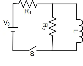
Immediately after closing switch S the magnetic flux through the inductor start to increase. Doe to the Lenz's law inductor opposes this rapidly changing flux by creating an induced current in the opposite direction of the circuit current. So at this moment, the branch of a circuit containing inductance doesn't appear in the calculation as if the inductor has infinite resistance! Therefore, by omitting the inductor branch, the circuit has only two resistors in series which their equivalence resistor is $R_{eq}=R_1+R_2$. Using Ohm's law, we obtain the current through the circuit \[I=\frac{V}{R_{eq}}=\frac{V_0}{R_1+R_2}\]
The correct answer is D.
Radio receivers are usually tuned by adjusting the capacitor of an $\mathrm{LC}$ circuit. If $\mathrm{C\ =\ }{\mathrm{C}}_{\mathrm{1}}$ for a frequency of $\mathrm{600\ kHz}$, then for a frequency of $\mathrm{1200\ kHz}$ one must adjust $C$ to:
(a) $C_1/2$
(b) $C_1/4$
(c) $2C_1$
(d) $4C_1$
(e) $\sqrt{2}C_1$
Any circuit that contains $L$,$R$ and $C$ undergoes electrical oscillations with angular frequency $\omega $. In $LC$ circuit this angular frequency is determined by $\omega =1/\sqrt{LC}$. Tuning a radio receiver means the angular frequency of $LC$ circuit equals to the desired frequency. Here there are two desired frequency $600\ \mathrm{kHz}$ and $1200\ \mathrm{kHz}$. Let $C=C_1$ be the capacitance of the $LC$ circuit at frequency $600\ \mathrm{kHz}$ and $C=C^{'}$ that of frequency $1200\ \mathrm{kHz}$. Therefore
\[\frac{{\omega }_1}{{\omega }^{'}}=\sqrt{\frac{C^{'}}{C_1}}\]
\[\frac{600}{1200}=\sqrt{\frac{C^{'}}{C_1}}\Rightarrow \frac{C^{'}}{C_1}=\frac{1}{4}\Rightarrow C^{'}=\frac{C_1}{4}\]
The correct answer is B.
An RLC series circuit, connected to a source $EMF$, is at resonance. Then:
(a) the voltage across $R$ zero
(b) the voltage across $R$ equals the applied voltage
(c) the voltage across $C$ is zero
(d) the voltage across $L$ equals the applied voltage
(e) the applied voltage and current differ in phase by 90${}^\circ$
If an inductor of inductance $L$, and resistor of resistance R and a capacitor of capacitance $C$ are connected in series across the terminals of a source, an RLC series circuit forms.
Resonance in AC circuits implies a special frequency which is determined by the values of resistance, capacitance and inductance. Let us suppose an RLC series circuit is connected across an ac source of constant voltage $V$ but adjustable angular frequency $\omega $. In ac circuits there is some important concepts such as impedance which plays the role of resistance $R$ in dc circuits and is defined as the ratio of the voltage amplitude across the circuit to the current amplitude in the circuit $Z=V/I$ or
\[Z=\sqrt{R^2+\left(X_L-X_C\right)^2}=\sqrt{R^2+{\left(\omega L-\left(\frac{1}{\omega C}\right)\right)}^2}\]
Where $X_L=\omega L$ and $X_C=1/\omega C$ are inductive and capacitive reactances of the inductor and capacitor of the circuit, respectively. Their SI units are ohm, the same as for resistance! At resonance which is occurred at resonance angular frequency ${\omega }_0$, the inductive and capacitive reactances are equal
\[X_L=X_C\Rightarrow \ {\omega }_0=\frac{1}{\sqrt{LC}}\]
One of the other important properties of RLC circuits at resonance is that the total voltage across the L-C combination is exactly zero! As a result, the voltage across the resistor is equal to the source voltage.
The correct answer is B.
The impedance of the circuit shown is:
(a) $21\mathrm{\Omega }$
(b) $50\ \mathrm{\Omega }$
(c) $63\ \mathrm{\Omega }$
(d) $65\ \mathrm{\Omega }$
(e) $98\ \mathrm{\Omega }$
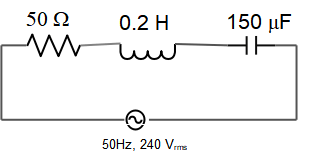
Impedance $Z$ of an ac circuit is defined as the ratio of the maximum voltage (voltage amplitude) across the circuit to the maximum current (current amplitude) in the circuit and plays the role of resistance in dc circuits.
\[Z=\frac{\mathrm{\Delta }V_{max}}{I_{max}}\]
The impedance of an RLC series circuit is $Z=\sqrt{R^2+{\left(X_L-X_C\right)}^2}$, where $X_L=L\omega $ and $X_C=1/\omega C$ are the inductive and capacitive reactance of inductor and capacitor. $\omega $ is the frequency of the ac circuit.
The frequency of this circuit is $f=50\ \mathrm{Hz}$ so its angular frequency is $\omega =2\pi f=100\,\pi\,s^{-1}$ therefore, \[X_L=\left(0.2\right)\left(100\pi \right)=20\pi\, \mathrm{\Omega }\] and \[X_C=\frac{1}{\omega C}=\frac{1}{\left(100\pi \right)\left(150\times {10}^{-6}\right)}=21.22\,\mathrm{\Omega }\] Therefore \begin{align*} Z&=\sqrt{R^2+{\left(X_L-X_C\right)}^2}\\&=\sqrt{{50}^2+{\left(20\pi -133.3\right)}^2}\\&=65.05\quad{\rm\Omega}\end{align*}
The correct answer is D.
© 2015 All rights reserved. by Physexams.com
AP® is a trademark registered by the College Board, which is not affiliated with, and does not endorse, this website.