RL Circuits Problems with Answers
In this tutorial, we explore RL circuits, key formulas, and solve practical problems. Ideal for high school students, this guide offers clear explanations and step-by-step solutions.
RL Series Circuit Fact Sheet:
Any circuit that includes a resistor, an inductor, and an emf (electromotive force) in series or parallel is called an RL circuit.
To solve RL circuit problems, you should apply Kirchhoff's voltage law to derive the necessary equations.
An inductor with self-inductance $L$ is used in a single-loop circuit to prevent the current from reaching its maximum value instantaneously.
RL Circuits Formulas
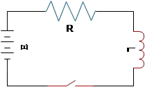
Case I: If we have a single-loop circuit in which components $R$ and $L$ are connected to a battery with emf $\mathcal{E}$, then the current in this RL circuit is given by formula: \[I=\frac{\mathcal{E}}{R}\left(1-e^{(-Rt/L)}\right)=I_{max}\left(1-e^{-t/\tau}\right)\] Where:
$\mathcal{E}$ is the emf of the battery in volts
$L$ is the self-inductance of the inductor in henry ($H$)
$R$ is the resistance of the resistor in ohms ($\Omega$)
$e$ is the base of the natural logarithm, $e=2.71828$
$\tau$, called the time constant, has units of time in seconds and is the time it takes the current in the circuits to reach $63.2\%$ of its maximum (final) value $I_{max}$. It defines as $\tau=\frac{L}{R}$.
Note: for an RC circuit, the time constant is defined as $\tau=RC$.
Case II: If the energy source, the battery, is removed from the circuit by opening a switch, then the current does not drop to zero through the resistor instantaneously but takes some time. In this case, the current at any time is given by: \[I=I_0 e^{-t/\tau}\] where $I_0$ is the initial current before the switch is opened.
In this case, the time constant is interpreted as the time for the current to decrease to $37\%$ of its original value.
RL Circuit Solved Problems
Problem (1): A solenoid with an inductance of 25 mH and resistance of ${8\,\rm \Omega}$ are connected to the terminals of a 6-V battery in series. There is also a switch in the circuit.
(a) Immediately after the switch is closed, find the potential drop across the resistor.
(b) Find the final current in the circuit.
(c) Find the time constant of the circuit.
(d) Find the current after one time constant has elapsed.
Solution: Recall that the current in an RL circuit at any instant of time is given by: \[I(t)=\frac{\mathcal{E}}{R}(1-e^{-Rt/L})\]
(a) The potential drop across the resistor in an RL circuit is given by $\Delta V=IR$. By setting $t=0$ in the equation for current, we find the current just after closing the switch as follows: \[I(t=0)=\frac{\mathcal{E}}{R}(1-e^{-R(0)/L})=0\] Thus, the voltage drop across the resistor is $\Delta V_R=I(t=0)R=0$ immediately after the switch is closed.
Alternative: Immediately after the switch is closed, the inductor acts like an open circuit. This is because it opposes any sudden change in current. Since no current flows initially, there is no voltage drop across the resistor.
(b) In an RL circuit, the final or maximum current is found by: $I_f=\frac{\mathcal{E}}{R}$. The final current in this single-loop circuit is: \[I_f=\frac{6}{8}=0.75\quad {\rm A}\] After a long time, the inductor acts like a normal wire. This means the only resistance in the circuit is the resistor itself.
(c) By definition, the time constant in an RL circuit is the time it takes for the current to reach $63.2\%$ of its final value. Therefore, \[\tau=\frac LR=\frac {25\times 10^{-3}}{8}=3.125\,{\rm ms}\]
(d) The current after on time constant, $I(t=\tau)$, is calculated as follows: \begin{align*} I(t)&=\frac{\mathcal{E}}{R}(1-e^{-t/\tau})\\ \\&=\frac{6}{8}(1-e^{-\tau/\tau})\\ \\&=0.75(1-e^{-1})\\ \\&=0.474\quad {\rm A}\end{align*}
Be sure to check the following article before taking your AP Physics C exam:
AP Physics Circuits Practice Problems with Solutions
Problem (2): A $5\,{\rm mH}$-inductor, a $15\,{\rm \Omega}$-resistor are connected across a $12\,{\rm V}$- battery with negligible internal resistance in series.
(a) What is the final current in the circuit?
(b) What is the time constant?
(c) What is the current after two time constants have elapsed?
(d) What is the potential drop across the resistance after two time constants?
(e) What is the potential drop across the inductor after two time constants?
Solution: The master formula for the current in RL circuits when connected to a source of energy (battery) is: \[I(t)=\frac{\mathcal{E}}{R}(1-e^{-Rt/L})\]
(a) the final current is obtained after a long time, once the inductor reaches a steady state and behaves effectively like a normal wire. In such a situation, Ohm's law gives the current in the circuit as follows: \[I_f=\frac{12}{15}=0.8\quad {\rm A}\]
(b) The time when the current reaches $63.2\%$ of its final value is the time constant of the RL circuit, i.e., $I(t=\tau)=0.632I_f$. Thus, we have \[\tau=\frac{L}{R}=\frac{5\times 10^{-3}}{15}=333\quad {\rm \mu s}\] where $\mu$ denotes microseconds, $1\mu s=10^{-6}\,{\rm s}$.
(c) Setting $t=2\tau$ in the current equation above, we get: \begin{align*} I(t=2\tau)&=I_f(1-e^{-t/\tau})\\ \\&=0.8(1-e^{-2\tau/\tau})\\ \\&=0.8(1-e^{-2})\\ \\&=0.691\quad {\rm A}\end{align*} This means that after $666\,{\rm \mu s}$, the current reaches $86.4\%$ of its final value, which is $0.691\,{\rm A}$.
(d) The potential difference across the resistor is $\Delta V_R=I(t)R$. Thus, after two time constants, we have: \begin{align*}\Delta V_R&=I(t=2\tau)R\\&=0.691\times 15 \\&=10.365\quad{\rm V}\end{align*}
(e) Applying Kirchhoff's voltage rule around the circuit, we obtain: \[\mathcal{E}-\Delta V_R-\Delta V_L=0\] where $\Delta V_L$ is the voltage across the inductor at any instant of time. In the previous part, we calculated the $\Delta V_R$ after two time constants, so we have: \begin{gather*} \mathcal{E}-\Delta V_R-\Delta V_L=0 \\ 12-10.36-\Delta V_L=0 \\ \Rightarrow \Delta V_L=1.635\quad{\rm V}\end{gather*} Note that $\mathcal{E}$ is the emf of the battery in the circuit.
Alternative: The voltage across the inductor in an RL circuit decays exponentially according to the following equation: \[V_L (t)=V_0 e^{-t/\tau}\] where $V_0$ is the initial voltage across the inductor (equal to the battery voltage in this case, 12 V). Setting $t=2\tau$ in the above equation gives us the previous result.
Problem (3): Consider a series circuit including a $4\,{\rm \Omega}$, a $16\,{\rm mH}$-inductor, and a power supply of 9 volts.
(a) Find the time constant of the RL series circuit.
(b) Find the current in the circuit $100\,{\rm \mu s}$ after the switch is closed.
(c) How many time constants does it take for the current to reach $99.9\%$ of its final value?
Solution: Given data: $R=4\,{\rm \Omega}$, $L=16\,{\rm mH}$, $\mathcal{E}=9\,{\rm V}$.
(a) The time constant is the ratio of the inductance to the resistance in an RL circuit. Thus, \[\tau=\frac{L}{R}=\frac{16\times 10^{-3}}{4}=4\,{\rm ms}\] This is the time when the current reaches $63.2\%$ of its final value.
(b) The current in an RL series circuit is given by: \begin{align*} I(t)&=\frac{\mathcal{E}}{R}(1-e^{-t/\tau}) \\ \\&=\frac{9}{4}\left(1-e^{-\frac{100\times 10^{-6}}{4\times 10^{-3}}}\right)\\ \\&=55.5\quad {\rm mA}\end{align*}
(c) In this part, the unknown is time. To find it, we must solve the equation $I(t)=0.999I_f$ for $t$. Thus, we have: \begin{gather*} I=I_f (1-e^{-t/\tau})\\ \\ e^{-t/\tau}=\left(1-\frac{I}{I_f}\right)\end{gather*} Taking the natural logarithms of both sides gives: \[-\frac{t}{\tau}=\ln \left(1-\frac{I}{I_f}\right)\] Thus, by arranging and substituting the known values into the equation, we obtain: \begin{align*} t&=-\tau \ln \left(1-\frac{I}{I_f}\right) \\ \\&=-\tau\ln(1-0.999) \\ \\ &=6.9\tau \end{align*} In other words, it takes $6.9\times 4\,{\rm ms}=27.6\,{\rm ms}$ for the current to reach nearly its final value, which is relatively fast.
Problem (4): A 12-V battery is in series with a resistor of $3\,{\rm \Omega}$ and an inductor with unknown inductance.
(a) After a long time, find the current in the circuit.
(b) What is the current after one time constant?
(c) What is the voltage drop across the inductor after one time constant?
(d) Suppose the time constant of this RL circuit is $0.3\,{\rm s}$. Find the inductance of the circuit.
Solution:
(a) Recall that the current in the RL series reaches its final or maximum value after a long time. You can show this by letting $t$ approach infinity in the current formula, resulting in: $I_f=\mathcal{E}/R$. Thus, the final current is \[I_f=\frac{\mathcal{E}}{R}=\frac{12}{3}=4\quad {\rm A}\] Note: In an RL circuit with a battery, the time constant has a different meaning compared to an RL circuit without a battery.
(b) Setting $t=\tau$ in the current equation, we have \begin{align*} I&=I_f(1-e^{-t/\tau})\\ \\ &=4(1-e^{-\tau/\tau})\\ \\&=4(1-e^{-1})\\ \\ &=4\times 0.632 \\ \\&=2.528\quad {\rm A}\end{align*}
(c) From Kirchhoff's voltage rule, we have: $\mathcal{E}-\Delta V_R -\Delta V_L=0$. To find $\Delta V_L$, we must first determine $\Delta V_R$. From the section of Ohm's law problems the voltage drop across the resistor at time $t=\tau$ is: \begin{align*}\Delta V_R &=I(t)R\\&=2.528\times 3\\&=7.584\quad {\rm V}\end{align*} Next, substituting this into Kirchhoff's voltage rule expression, we get: \begin{gather*}\mathcal{E}-\Delta V_R -\Delta V_L=0\\ 12-(7.584)-\Delta V_L=0\\ \Rightarrow \Delta V_L=4.416\quad {\rm V}\end{gather*}
(d) The time constant in a series RL circuit is defined as $\tau=L/R$. Thus, using this formula and solving for inductance, we get \begin{align*}L&= R\tau \\ &=3\times 0.3\\&=0.9\quad {\rm H}\end{align*}
Problem (5): In a circuit containing a $35\,\rm V$ power supply, a $45\,\rm \Omega$ resistor, and a solenoid of inductance $1.25\,\rm mH$ with negligible resistance, all connected in a series with an open switch. The switch is suddenly closed.
(a) How long after closing the switch will the current through the circuit reach two-thirds of its maximum value?
(b) How long after closing the switch will the energy stored in the solenoid (inductor) reach two-thirds of its maximum value?
Solution: This problem concerns the growth of current in an RL circuit after closing a switch. In these cases, the maximum current in the circuit is given by $I=\frac{\mathcal E}{R}$. As you can see, the final current is independent of the inductance, because after a very long time, the solenoid (or inductor) behaves like a normal wire in the circuit.
(a) The current $i$ in an RL circuit with emf at any moment after closing the switch is given by: \[i=I_f \left(1-e^{-(R/L)t}\right) \] where $I_f$ is the final current. We must solve this equation for $t$, the only unknown quantity. Taking the natural logarithms of both sides and manipulating the equation gives: \begin{gather*} e^{-(R/L)t}=1-\frac iI \\\\ \Rightarrow \boxed{t=-\frac LR \ln \left(1-\frac iI\right)}\end{gather*} Substituting $i=\frac 23 I$ into the above expression yields: \begin{align*} t&=-\frac{1.25\times 10^3}{45}\ln\left(1-\frac{2/3 I}{I}\right) \\\\ &=30.5\,\rm s\end{align*} Therefore, about $30$ seconds after closing the switch, the current in the circuit reaches two-thirds of its final value.
(b) The total energy stored in an inductor with inductance $L$ is given by $U=\frac 12 Li^2$. After closing the switch, the current increases from zero to its final value. Substituting the current value at any time into this equation gives the energy stored in the inductor at any instant: \[U=U_{max}\left(1-e^{(-R/L)t}\right)^2\] where $U_{max}=\frac 12 LI^2$ is the maximum stored energy. Taking the natural logarithms of both sides and rearranging gives the time $t$ in terms of the other given quantities. \begin{align*} t&=-\frac LR \ln \left(1-\left(\frac{U}{U_{max}}\right)^2\right) \\\\ &=-\frac{1.25\times 10^3}{45}\ln\left(1-\left(\frac{2/3 U_{max}}{U_{max}}\right)^2\right) \\\\ &=16.3\,\rm s\end{align*}
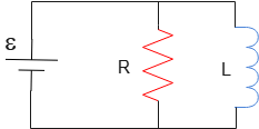
Problem (6): In a parallel RL circuit as below, after the switch is closed a power supply has been designed so that a constant current passes through it.
(a) What will the current through the inductor at any time be?
(b) At what time does the current through the resistor equal to the current through the inductor?
Solution: This is an interesting and challenging question whose solution can be used to address AP Physics C questions on this topic.
Unlike previous problems, in this case, the inductor and resistor are connected in parallel. Before solving, it's crucial to remember these points.
(1) Inductor behavior: Immediately after closing a switch in an inductor-containing circuit, the inductor acts like an open circuit, and no current flows through that branch.
(2) Parallel circuit voltage: In any circuit, components in parallel with a battery share the same voltage as the battery. Here, \[\mathcal E=V_{ad}=V_{bc}\] where $V_{ad}=iR$ and $V_{bc}=L\frac{di}{dt}$ represents the voltage (potential difference) across the inductor at any time.
(a) By applying voltage and current rules from Kirchhoff's law problems and solving the resulting equation, we finally obtain the following expression for the current at any time in an RL parallel circuit. \[I=I_{max}\left(1-e^{-(R/L)t}\right)\] where $I_{max}=\mathcal E/R$.
As you noticed, this equation is identical to the current equation in an RL series circuit.
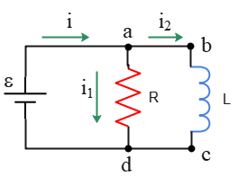
(b) Kirchhoff's junction rule at point $a$ gives \[i=i_1+i_2\] where $i$ is the battery current. Assuming zero internal resistance for the inductor, the equivalent resistance of the circuit is $R_{eq}=R$. Applying Ohm's law gives us the current through the battery as: \[i=\frac{\mathcal E}{R_{eq}}=\boxed{\frac{\mathcal E}{R}}\] We are asked to find the moment that the current through the resistor, $i_1$, is equal to the current through the inductor, $i_2$, i.e., $i_1=i_2$.
Substituting this condition into the expression obtained from the junction rule above and solving for $t$ gives: \begin{gather*} i=i_1+i_2 \\\\ i=i_2+i_2 \\\\ \frac{\mathcal E}{R}=2\times \frac{\mathcal E}{R}\left(1-e^{-(R/L)t}\right) \\\\ e^{-(R/L)t}=\frac 12 \\\\ -\frac RL t=\ln 2^{-1} \\\\ \Rightarrow \boxed{t=\frac LR \ln 2}\end{gather*} In the fifth line, we took the natural logarithm of both sides.
There are also some problems with inductance that is related to the RL series circuits.
Author: Dr. Ali Nemati
Date Published: 3/13/2021
Updated: April 26, 2023
© 2015 All rights reserved. by Physexams.com
AP® is a trademark registered by the College Board, which is not affiliated with, and does not endorse, this website.