Solved Problems
A 202-turns of wire exist on a 92.6 cm long solenoid. This solenoid produces a magnetic field of 2.34 gauss at its center.
(a) What is the current flowing through the coiled wire of this solenoid?
(b) If this solenoid has a diameter of $12.2\rm{\ cm}$ and the B-field is uniform inside this solenoid, what is the magnetic flux through one of the turns inside this solenoid?
(a) The magnetic field inside a solenoid along the central axes is $B={\mu }_0nI$ where $n=N/L$ is the number of turns per unit length of the solenoid.
First, convert the magnetic field from gauss to the Tesla and next find the $n$ \begin{gather*} 2.34\,G \times \left(\rm{\frac{1\, T}{10^{4}\,G}}\right)=2.34\times 10^{-4}\quad {\rm T} \\ \\ n=\frac{N}{L}=\frac{202}{0.926}=218\quad {\rm m^{-1}}\end{gather*} Therefore, using the formula of magnetic field inside the solenoid $B=\mu_0 nI$ and solving for the current , we get \[I=\frac{2.34\times {10}^{-4}}{\left(4\pi \times {10}^{-7}\right)(218)}=0.854\quad {\rm A}\]
(b) The total magnetic flux through a solenoid with $N$ turns is defined by ${\rm{\Phi }}_M=NBA$ so first find the cross-section of the solenoid
\begin{align*}A&=\pi r^2\\ \\&=\pi \left(\frac d2\right)^2\\ \\&=\frac{\pi}4(0.122)^2\\ \\&=1.17\times 10^{-2}\quad {\rm m^2}\end{align*}
\begin{align*}\Phi_m&=BA\\&=(2.34\times 10^{-4})(1.7\times 10^{-2})\\ &=2.74\times {10}^{-6}\quad {\rm Wb}\end{align*}
A proton ($q=+e$) moves in the positive $x$ direction, in a region with an electromagnetic field. Its velocity is $\vec{v}=\left(2\times {10}^6\frac{\mathrm{m}}{\mathrm{s}}\right)\hat{i}$. The fields are $\vec{E}=\left(1200\frac{\mathrm{N}}{\mathrm{C}}\right)\hat{j}$ and $\vec{B}=\left(2\mathrm{mT}\right)\hat{i}+\left(3\mathrm{mT}\right)\hat{k}$. Find the magnitude and direction of the electric, magnetic and total forces acting on the proton. What speed $v$ would result in a zero total force?
The electric force defined by $\vec{F}=q\vec{E}$ so \begin{align*} {\vec{F}}_E&=\left(1.6\times {10}^{-19}{\rm C}\right)(1200\hat j)\\ \\&=1.92\times {10}^{-16}\,\hat j \quad {\rm N}\end{align*}
The force that exerts on a moving charged particle with velocity $\vec v$ in a magnetic field $\vec B$ is found by
\begin{align*} \vec{F}&=q\vec{v}\times \vec{B}\\ \\&=(1.6\times 10^{-19})\left(2\times 10^{6}\,\hat i\right)\times \left(2\times {10}^{-3}\hat{i}+3\times {10}^{-3}\hat{k}\right)\\ \\&=-9.6\times {10}^{-16}\,\hat{j}\quad {\rm N}\end{align*}
The total force is determined by the vector sum of them as \begin{align*}\vec{F}&={\vec{F}}_E+{\vec{F}}_B\\ \\ &=1.92\times {10}^{-16}\,\hat{j}+(-9.6\times {10}^{-16})\,\hat{j}\\ \\&=-7.68\times {10}^{-16}\,\hat{j}\quad {\rm N}\end{align*}
Now write the net force above in the component form and then set $F=0$ to find the desired speed $v$ as follows: \begin{gather*}F=eE_y-ev_xB_z=0\\ \\ \Rightarrow v_x=\frac{E_y}{B_z}=\frac{1200}{0.003}=4\times {10}^5\quad {\rm m/s}\\ \\ \Rightarrow \vec{v}=4\times {10}^5\,(\hat{i}) \quad{\rm m/s}\end{gather*}
A point charge $Q$ moves on the $x$ axis in the positive direction with a speed of $280\ \mathrm{m/s}$. A point P is on the $y$ axis at $y=+70\, \mathrm{mm}$. The magnetic field produced at the point P, as the charge moves through the origin, is equal to $-0.30\, \mu{\rm T\ }\hat{\mathrm{k}}$. What is the charge $Q$?
Note: a moving point charge $q$ with velocity $\vec{v}$ produces a magnetic field $\vec{B}$ in space that is given by
\begin{gather*} \vec{B}=\frac{{\mu }_0}{4\pi }\frac{q\vec{v}\times \hat{r}}{r^2}\\ \\ {\mu }_0=4\pi \times {10}^{-7}\frac{\mathrm{T.m}}{\mathrm{A}}\end{gather*} Where $\hat{r}$ is the unit vector that points to the point P. (in this problem $\hat{r}=\hat{j}$)
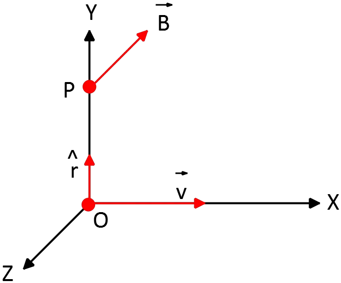
When the particle is instantaneously at origin, we have $\vec{v}=280\ \hat{i}\ ,\ {\vec{B}}_P=-0.30\,\mu\mathrm{T\ }\hat{k}$ so
\begin{align*}\vec{B}&=\frac{{\mu }_0}{4\pi }\frac{q\vec{v}\times \hat{r}}{r^2}\\ \\ -0.30\times {10}^{-6}\hat{k}&={10}^{-7}\frac{Q\left(280\hat{i}\times \hat{j}\right)}{{\left(0.070\right)}^2}\\ \\&=5.71\times {10}^{-3}Q\hat{k}\\ \\\Rightarrow Q&=52.5\quad {\rm \mu C}\end{align*}
A long, straight wire with $3.0\ \mathrm{A}$ current flowing through it produces magnetic field strength $1.0\ \mathrm{T}$ at its surface. If the wire has a radius $R$, where within the wire is the field strength equal to $36\%$ of the field strength at the surface of the wire? Assume that the current density is uniform throughout the wire.
First by using the Ampere's law find the magnetic field inside the wire as
$\oint_C{\vec{B}.d\vec{l}}={\mu }_0I_{enc}$ where $I_{enc}$ is the current passing through the surface enclosed by the curve $C$. By definition $I_{enc}=JA=J(\pi r^2)$. Therefore,
\[\oint_C{\vec{B}.d\vec{l}}={\mu }_0I_{enc}\Rightarrow B_r\left(2\pi r\right)={\mu }_0\left(\pi r^2\right)J_r\Rightarrow B_r={\mu }_0\frac{r}{2}J_r\]
Since the current density passing through each surface is constant i.e. $J_r=J_R=I/\pi R^2$ so
\[\Rightarrow \ B_r=\frac{{\mu }_0I}{2\pi R^2}r\ \ ,\ \ r<R\]
Substitute $r=R$ to find the magnetic field at the surface of the wire i.e. $B_R={\mu }_0I/2\pi R$
\[B_r=0.36B_R\Rightarrow \ \frac{{\mu }_0I}{2\pi R^2}r=0.36\frac{{\mu }_0I}{2\pi R}\mathrm{\Rightarrow }\mathrm{r=0.36\ R}\]
A particle with charge $-5.00\ \mathrm{C}$ initially moves at $\vec{v}=\left(1.00\ \hat{i}+7.00\hat{j}\right)\left(\frac{m}{s}\right)$. If it encounters a magnetic field $\vec{B}=10.00\ \mathrm{T\ }\hat{\mathrm{k}}$,find the magnetic force vector on the particle?
If a charged particle moves with velocity $\vec{v}$ in a magnetic field $\vec{B}$, then from the field exerts a force on it that is determined by $\vec{F}=q\ \vec{v}\times \vec{B}$. Therefor,
\begin{align*} \vec{F}&=q\ \vec{v}\times \vec{B}\\ &=\left(-5\right)\left(\hat{i}+7\hat{j}\right)\times \left(10\hat{k}\right)\\ &=-50\left(\hat{i}\times \hat{k}\right)-350\left(\hat{j}\times \hat{k}\right)\\ &=-50\ \left(-\hat{j}\right)-350\, \hat{i}\quad {\rm N} \end{align*}
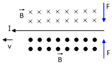
A horizontal wire has a $40\,\rm A$ current moving through it to the left. A $3.00\,\rm g$ particle, with a charge of $+6.00\ \mu \rm C$ is moving in a straight line horizontally in the direction of the current. Note that the particle's trajectory is also horizontal, and therefore parallel to the wire, it maintains a constant distance of $8.00\,\rm mm$ from the wire.
(a) How fast is the particle moving?
(b) Is the particle above or below the wire?
(a) Since the particle moves without deflecting its path, it is in equilibrium. Two forces acting on it. One is the gravity and the other is the magnetic force. But gravity is in the $-y$ direction so the magnetic force must be in the $+y$ direction. Using the right-hand rule, we can infer that the particle must move below the wire.
Right-hand rule: point thumb in direction of the velocity and fingers in the magnetic field direction then your palm direction is the direction of the magnetic force.
\begin{gather*} mg=qvB_{long\ wire}=qv\left(\frac{{\mu }_0I}{2\pi r}\right)\\ \\ \Rightarrow v=\frac{2\pi rmg}{{\mu }_0qI}\end{gather*} Substituting the known values into the above, we get \begin{align*} v&=\frac{2\pi (0.008)(0.003)(9.8)}{\left(4\pi \times {10}^{-7}\right)\left(6\times {10}^{-6}\right)40}\\ \\ &=4.9\times {10}^6 \quad {\rm m/s}\end{align*}
(b) Stated above.
Assume that a lightning bolt can be represented a by long straight line of current. If $22.0\ \mathrm{C}$ of charge passes by in a time of $2.00\times {10}^{-3}$ seconds, what is the magnitude of the magnetic field at a distance of $50.0$ meters from the bolt?
By definition, the magnetic field of a long straight wire carrying current $I$ at distance $r$ from it is $B=\frac{{\mu }_0I}{2\pi r}$ so we must first find the current that passes through the wire.
\[I\left(t\right)=\frac{\mathrm{\Delta }q}{\mathrm{\Delta }t}=\frac{22}{2\times {10}^{-3}}=1.1\times {10}^2\mathrm{A}\]
\[B\left(r\right)=\frac{{\mu }_0I}{2\pi r}=4\pi \times {10}^{-7}\frac{1100}{2\pi \times 50}=44\times {10}^{-7}=440\, \mu\mathrm{T}\]
A $15.2\ \mathrm{MeV}$ cosmic ray positively charged ion has a mass of $3.45\times {10}^{-26}\, \mathrm{kg}$ moves in a circular orbit whose orbital plane is perpendicular to a uniform $2.88\times {10}^{-8}\mathrm{T}$ magnetic field.
(a) If the radius of this circular orbit is $9890\ \mathrm{km}$, what is the charge on this cosmic ray ion?
(b) Approximately how many electrons would this ion be deficit, that is how many extra electrons would this ion need to make it a natural particle?
(a) Since the particle moves in a circular orbit so there is a centripetal force that is provided by the magnetic force. By definition, this centripetal force is related to the velocity of the particle via \[F_c=m\frac{v^2}{r}\]
Now from the kinetic energy calculate the velocity of the charged particle
\begin{align*} K&=\frac{1}{2}mv^2\\ \\ \Rightarrow v&=\sqrt{\frac{2K}{m}}\\ \\&=\sqrt{\frac{2\times 15.2\times {10}^6\times 1.6\times {10}^{-19}}{3.45\times {10}^{-26}}}\\ \\&=1.19\times {10}^7\quad {\rm m/s}\end{align*} Therefore, we have \begin{gather*} F_c=F_{magnetic}=m\frac{v^2}{r}\\ \\ \Rightarrow q\vec{v}\times \vec{B}=\frac{mv^2}{r}\end{gather*} But the velocity is perpendicular to the magnetic force ($\theta =90{}^\circ $), therefore \begin{align*} qvB&=\frac{mv^2}{r}\\ \\ \Rightarrow q&=\frac{mv}{Br}\\ \\&=\frac{\left(3.45\times {10}^{-26}\right)\left(1.19\times {10}^7\right)}{\left(2.88\times {10}^{-8}\right)\left(9890\times {10}^3\right)}\\ \\&=1.44\times {10}^{-18}\quad \mathrm{C}\end{align*}
(b) From the relation $q=ne$ the above charge equals to the following number of electrons \begin{align*} q&=ne\\ \\ \Rightarrow n&=\frac{q}{e}\\ \\ &=\frac{1.44\times {10}^{-18}}{1.6\times {10}^{-19}}\\ \\&=9\end{align*} That is nine electrons must be added to this ion to make it natural.
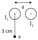
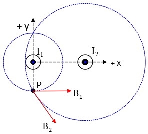
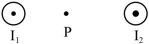
The following diagrams shows a pair of parallel wires carrying currents $I_1$ and $I_2$. $I_1=5.0\ A$ and $I_2=15.0\ \mathrm{A}$, $d=4.0\ \mathrm{cm}$
(a) At what point on a line between the two wires is the $\vec{B}$ field zero?
(b) What is the magnitude and direction of the $\vec{B}$ field at the point P located $3.0\ \mathrm{cm}$ directly below $I_1$?
(c) At point P, a third wire is placed carrying current $I_3=10\ \mathrm{A}$ parallel to both $I_1$ and $I_2$ but directed into the plane of the page from the edge view. What is the magnitude of the force this $2.0\ \mathrm{m}$ length third wire feels?
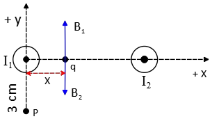
(a) Consider the desired point to be a distance $x$ from the wire $I_1$(along the line between the two currents ).
So the total magnetic fields due to the currents $I_1$ and $I_2$ are
\begin{gather*} {\vec{B}}_1=\frac{{\mu }_0I_1}{2\pi x}\hat{y} \\ \\ {\vec{B}}_2=\frac{{\mu }_0I_2}{2\pi \left(d-x\right)}\left(-\hat{y}\right)\\ \\\Rightarrow {\vec{B}}_q={\vec{B}}_1+{\vec{B}}_2 \\ \\ \Rightarrow {\vec{B}}_q=\frac{{\mu }_0}{2\pi }\left(\frac{I_1}{x}-\frac{I_2}{d-x}\right)\hat{y}\end{gather*} We want the ${\vec{B}}_P$ to be zero, so
\begin{gather*} {\vec{B}}_q=0\\ \\ \Rightarrow I_1\left(d-x\right)\\ \\ =I_2x\\ \\ \to x\left(I_2+I_1\right)=I_1d \\\ \\ \Rightarrow x=\frac{I_1}{I_1+I_2}d\end{gather*} Substituting the values get \begin{align*} x&=\frac{5}{5+15}(0.04)\\\\ &=0.01\quad {\rm m} \\ \\&=1\quad {\rm cm}\end{align*}
Note: the direction of magnetic field of a straight wire is determined by the right hand rule: put the thumb in the direction of current flow, the fingers curl in the direction of the magnetic field.
(b) Note: The direction of the magnetic field at a point around a straight wire is tangent to a circle with the center of the current-carrying wire (see figure below).
\begin{align*} B_1&=\frac{{\mu }_0I_1}{2\pi r_1}\\\\&=\frac{\left(4\pi \times {10}^{-7}\right)\left(5\right)}{2\pi \times 0.03}\\\\&=3.3\times {10}^{-5}\quad \mathrm{T}\\ \\ B_2&=\frac{{\mu }_0I_2}{2\pi r_2}\\ \\&=\frac{\left(4\pi \times {10}^{-7}\right)\left(15\right)}{2\pi \times \sqrt{{\left(0.03\right)}^2+{\left(0.04\right)}^2}}\\ \\&=6\times {10}^{-5}\quad \mathrm{T}\end{align*} From the right hand rule, $B_1$ is in the $x$ direction but $B_2$ makes an angle $\theta $ with the positive $x$ direction (below axes) so must be decomposed into $x$ and $y$ directions \begin{align*} B_{2x}&=B_2{\mathrm{cos} \theta}\\ \\&=\left(6\times {10}^{-5}\right)\left(\frac{0.03}{0.05}\right)\\ \\&=3.6\times {10}^{-5}\quad \mathrm{T}\\ \\ B_{2y}&=B_2{\mathrm{sin} \theta}\\ \\&=-\left(6\times {10}^{-5}\right)\left(\frac{0.04}{0.05}\right)\\ \\&=-4.8\times {10}^{-5}\quad \mathrm{T}\end{align*} Therefore, by applying the superposition principle, we have \begin{align*}{\vec{B}}_P&={\vec{B}}_1+{\vec{B}}_2\\&=\left(3.3+3.6\right)\times {10}^{-5}\hat{x}+4.8\times {10}^{-5}\left(-\hat{y}\right)\\ \\ \left|{\vec{B}}_P\right|&=\sqrt{B^2_{Px}+B^2_{Py}}\\ &=\sqrt{{\left(6.9\times {10}^{-5}\right)}^2+{\left(-4.8\times {10}^{-5}\right)}^2}\\&=8.4\times {10}^{-5}\quad \mathrm{T}\end{align*}
To find the direction of a vector with respect to the horizontal axis, use the equation below \begin{align*} \alpha &={\rm tan^{-1} \left(\frac{x\ comp.}{y\ comp.}\right)}\\ \\ &={\rm tan^{-1} \left(\frac{-4.8\times {10}^{-5}}{6.9\times {10}^{-5}}\right)}\\\\&={\rm -34.82^\circ}\end{align*}
Since $B_x>0\ and\ B_y<0$ so the resultant magnetic field lies in the fourth quadrant.
(c) In this point there is a net magnetic field due to the currents $I_1$ and $I_2$ that relates to the force exerted by these currents on a third current via\begin{align*}\vec{F}_P&=I_3{\vec{L}}_3\times {\vec{B}}_P\\&=(10)(2)\left(8.5\times {10}^{-5}\right)\\&=1.7\times {10}^{-3}\quad {\rm N}\end{align*}
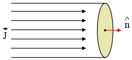
A long, straight, solid cylinder, oriented with its axis in the $z$ direction, carries a current whose current density is $\vec{J}$. The current, though symmetric about $z$ varies as $\vec{J}=\frac{2I_0}{\pi a^2}\left(1-{\left(\frac{r}{a}\right)}^2\right)$ for $r<R$ and $\vec{J}=0$ for $r>R$, where $a$ is the radius of the cylinder, $r$ is the radial distance from the cylinder axis and $I_0$ is the total charge.
(a) Now show that $I_0$ is the total current passing through the entire cross-section of the wire.
(b) Using Ampere's law, derive an expression for the magnitude of the magnetic field $\vec{B}$ in the regions $r>a$ and $r<a$
(a) By definition \begin{align*} I=\int{\vec{J}\cdot\hat{n}dA} &=\int^a_0{\frac{2I_0}{\pi a^2}\left(1-{\left(\frac{r}{a}\right)}^2\right)}\underbrace{2\pi rdr}_{dA}\\&=\frac{4I_0}{a^2}{\left(\frac{1}{2}r^2-\frac{r^4}{4a^2}\right)}^a_0=\frac{4I_0}{a^2}\left(\frac{1}{2}a^2-\frac{a^4}{4a^2}\right)=\frac{4I_0}{a^2}\frac{a^2}{4}=I_0\end{align*} In the above, the current density is in the direction of the unit vector normal to the surface area of cylinder. i.e. $\vec{J}.\hat{n}=\left|\vec{J}\right|\left|\hat{n}\right|{\mathrm{cos} 0{}^\circ \ }=\left|\vec{J}\right|$ As shown in the figure below
 (b) Ampere's law states that the circulation of the magnetic field around a curve $C$ is related to the current passing through the surface $S$ bounded by $C$ i.e.$\oint_C{\vec{B}.d\vec{l}}={\mu }_0I_{enc}$ where $I_{enc}$ is the current through any surface bounded by the curve $C$.
\begin{align*}I_{enc}&=\int{\vec{J}\cdot\hat{n}dA}\\ \\&=\int^r_0{\frac{2I_0}{\pi a^2}\left(1-{\left(\frac{r}{a}\right)}^2\right)}\underbrace{2\pi rdr}_{dA}\\ \\&=\frac{4I_0}{a^2}\left(\frac{1}{2}r^2-\frac{r^4}{4a^2}\right)\end{align*} and the left side of Ampere's law is \begin{gather*}\oint_C{\vec{B}\cdot d\vec{l}}=B\oint_C{dl}={\mu }_o I_{enc}\\ \\ \Rightarrow B=\frac{{\mu }_0I_{enc}}{2\pi r}\end{gather*} Therefore, for inside the cylinder we have,\begin{align*}B_{in}\left(r<a\right)&=\frac{{\mu }_0}{2\pi r}\frac{4I_0}{a^2}\left(\frac{1}{2}r^2-\frac{r^4}{4a^2}\right)\\ \\&=\frac{{\mu }_0I_0}{{\pi a}^2}\left(r-\frac{r^3}{2a^2}\right)\end{align*} and for outside the magnetic field is \begin{align*}B_{out}\left(r>a\right)&=\frac{{\mu }_0}{2\pi r}I_{tot}\\ \\&=\frac{{\mu }_0}{2\pi r}I_0\end{align*}
Positive charge $Q$ is distributed along the positive $y$ axis between $y=0$ and $y=a$. A negative point charge $-q$ lies on the positive $x$ axis, a 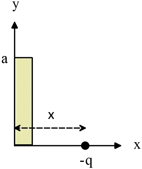 distance $x$ from the origin as shown in the figure.
(a) Calculate the $x$ and $y$ components of the electric field $E_x$ and $E_y$ produced by the charge distribution $Q$ at points on the positive $x$ axis.
(b) Calculate the $x$ and $y$ components of the force that the charge distribution $Q$ exerts on $q$.
(c) When $x\gg a$ derive simplified expressions for both $F_x$ and $F_y$. Hint: use the approximation that ${\left(1+x\right)}^n=1+nx$ when $x\ll 1$.
Hint: $\int{\frac{du}{{\left(u^2+a^2\right)}^{\frac{3}{2}}}}=\frac{u}{a^2\sqrt{u^2+a^2}}$ and $\int{\frac{u}{{\left(u^2+a^2\right)}^{\frac{3}{2}}}du\ }=-\frac{1}{\sqrt{u^2+a^2}}$
(a) Similar to previous problems, first find the electric field at the desired 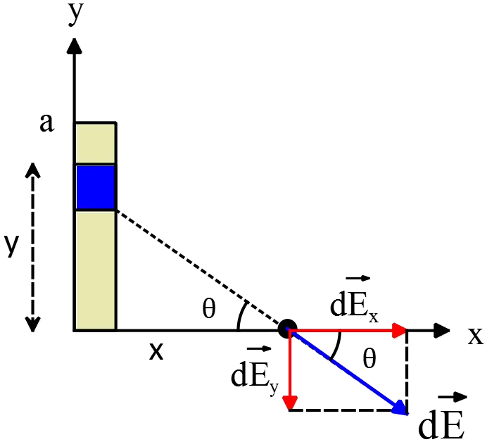 distance due to a positive charge element $dq$, then by integrating determine the total electric field.
\[d\vec{E}=d{\vec{E}}_x+d{\vec{E}}_y=\int{k\frac{dq}{r^2}\hat{r}}=k\int^a_0{\frac{\lambda dy}{x^2+y^2}\left({\mathrm{cos} \theta \ }\hat{x}+{\mathrm{sin} \theta \ }\left(-\hat{y}\right)\right)}\]
From the geometry ${\mathrm{sin} \theta \ }=\frac{y}{\sqrt{x^2+y^2}}$ and ${\mathrm{cos} \theta \ }=\frac{x}{\sqrt{x^2+y^2}}$ so
\begin{align*} \vec{E} &=k\int^a_0{\frac{\lambda dy}{x^2+y^2}\left(\frac{x}{\sqrt{x^2+y^2}}\hat{x}+\frac{y}{\sqrt{x^2+y^2}}\left(-\hat{y}\right)\right)}\\ &= k\lambda {\left(\frac{xy}{x^2\sqrt{x^2+y^2}}\hat{x}+\frac{-1}{\sqrt{x^2+y^2}}\left(-\hat{y}\right)\right)}^a_0\\&=k\lambda \left(\underbrace{\frac{a}{x\sqrt{x^2+a^2}}}_{E_x}\hat{x}+\underbrace{\left(\frac{1}{\sqrt{x^2+a^2}}-\frac{1}{x}\right)}_{E_y}\hat{y}\right) \end{align*}
(b) By definition, $\vec{F}=q\vec{E}$ so
\[F_x=\left(-q\right)E_x=-qk\lambda \ \frac{a}{x\sqrt{x^2+a^2}}=-\frac{kQq}{x\sqrt{x^2+a^2}}\]
\[F_y=\left(-q\right)E_y=-qk\lambda \left(\frac{1}{\sqrt{x^2+a^2}}-\frac{1}{x}\right)=-\frac{kQq}{a}\left(\frac{1}{\sqrt{x^2+a^2}}-\frac{1}{x}\right)\]
In above we have used the fact that $\lambda =\frac{charge}{length}=\frac{Q}{a}$
(c) If $x\gg a$ then we have from the approximation below
\[\frac{1}{\sqrt{x^2+a^2}}=\frac{1}{\sqrt{x^2\left(1+\frac{a^2}{x^2}\right)}}=\frac{1}{x}{\left(1+\frac{a^2}{x^2}\right)}^{-\frac{1}{2}}=\frac{1}{x}\left(1-\frac{a^2}{2x^2}\right)\]
\[F_x=-\frac{kQq}{x\sqrt{x^2+a^2}}=-\frac{kQq}{x}\frac{1}{x}\left(1-\frac{a^2}{2x^2}\right)=-\frac{kQq}{x^2}\left(1-\frac{a^2}{{2x}^2}\right)\]
\[F_y=-\frac{kQq}{a}\left(\frac{1}{x}\left(1-\frac{a^2}{2x^2}\right)-\frac{1}{x}\right)=+\frac{kqQ}{2x^3}a\]
A charge of $+0.2\ \mathrm{C}$ and mass $0.025\ \mathrm{kg}$ is moving as 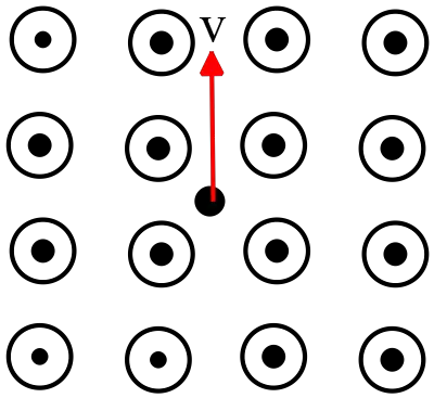 shown in the magnetic field of $2.5\ \mathrm{T}$ directed out of the page. ($v=3.5\ \mathrm{m/s}$)
(a) In the figure, sketch the trajectory of the charge.
(b) What is the magnitude force exerted on the charge( magnitude and direction)
(c) What would the radius of the trajectory be?
(a) Right-hand rule for a moving charged particle in a magnetic field: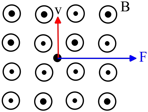
Point your right four fingers in the direction of the velocity of the particle so that your palm is directed in the magnetic field direction then the thumb shows the force.
Note: The force on a negative charge is in exactly the opposite direction to that of on a positive charge
(b) Recall from the magnetic field problems section that the force exerted on a charged particle with a velocity $v$ in a uniform magnetic field $B$ is
$\vec{F}=q\,\vec{v}\times \vec B=qvB\,{\mathrm{sin} 90\ }=0.2\times 3.5\times 2.5=1.75\ \mathrm{N}$ to the right (right hand rule).
(c) In the circular motion questions section, we find out that when a particle moves around a circle it experiences a centripetal force. In this problem this force provided by the magnetic field.
\begin{gather*} \Sigma F_r=ma_r=\frac{mv^2}{r} \\\\ F_B=F_r \\\\ \Rightarrow qvB=\frac{mv^2}{r} \end{gather*} Solving the above expression for $r$ and substituting the numerical values into it gives \begin{align*} r&=\frac{mv}{qB} \\\\ &=\frac{(0.025)(3.5)}{(0.2)(2.5)} \\\\ &=0.175\quad \rm m \\\\ &=17.5\quad \rm cm\end{align*}
The figure shows two parallel wires carrying currents $I_13.5\mathrm{A}$ and $I_2=4\mathrm{A}$, both out of the page, separated by a distance of $20\ \mathrm{cm}$.
(a) Sketch the direction of the magnetic fields from wires $1$ and $2$ at point $P$.
(b) Determine the net B field at a point (P) $5\, \mathrm{cm}$ right of wire $1$.
(c) Determine the magnitude and direction of the forced exerted on wire 2 from wire 1.
(a) Right hand rule for finding the direction of the magnetic field around a 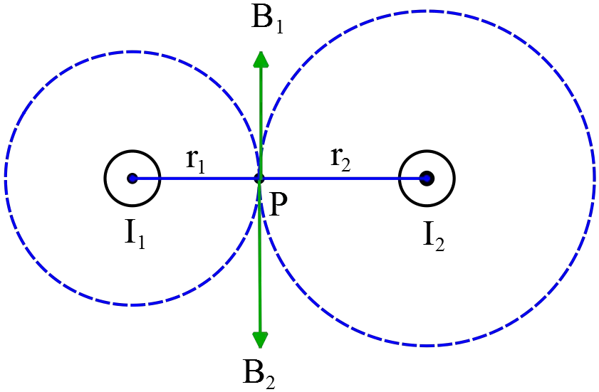 current carrying wire: point your thumb in the direction of the conventional current, then curl your fingers around the wire, they point in the direction of the magnetic field. (figure from Wikipedia)
(b) The magnetic field of a current carrying wire at distance $r$ is given by $B={\mu }_0I/2\pi r$. so
$$B_1=\frac{{\mu }_0}{2\pi }\frac{I_1}{r_1}=2\times {10}^{-7}\left(\frac{3.5}{0.05}\right)=1.4\times {10}^{-5}\mathrm{T} \qquad \text{Up direction}$$
$$B_2=\frac{{\mu }_0}{2\pi }\frac{I_2}{r_2}=2\times {10}^{-7}\left(\frac{4}{0.15}\right)=5.3\times {10}^{-6}\mathrm{T} \qquad \text{Down direction} $$
$$\vec{B}={\vec{B}}_1+{\vec{B}}_2=+8.67\times {10}^{-6}\mathrm{T} \qquad \text{Up direction}$$
(c) The force exerted on a line segment $l$ with current $I$ in a magnetic field $B$ is given by
\[\vec{F}=I\vec{l}\times \vec{B}\]
\[{\vec{F}}_2=I_2{\vec{B}}_1\times {\vec{l}}_2=I_2l_2B_1{\mathrm{sin} 90{}^\circ \ }=I_2\frac{{\mu }_0}{2\pi }\frac{I_1}{r}l_2=2\times {10}^{-7}\frac{3.5\times 4}{0.2}=1.4\times {10}^{-5}l_2\]
\[\Rightarrow \frac{F_2}{l_2}=1.4\times {10}^{-5}\mathrm{N/m}\]
An airplane with a speed $v$ is flying at the same altitude of a high voltage cable 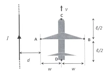 carrying a current $I$ as shown in the figure. Determine the following potential differences :$V_{BA}\ ,\ V_{CD}\ ,\ V_{CA}$. (notation: $V_{ij}=V_i-V_j$)
Since the plane flies on $xy$ plane, the magnetic field produced by the wire at distance $y$is given by
\[\vec{B}\left(y\right)=\frac{{\mu }_0I}{2\pi y}\hat{k}\]
First, consider a conductor bar with width $2w$ that moves in the magnetic field of the wire. Find the force exerted on it and then use the definition of the potential electric field to determine the potential difference between any points.
The force on a charged rod is $\vec{F}=q\vec{v}\times \vec{B}=qv\left(\hat{i}\right)\times B\left(\hat{k}\right)=qvB\left(-\hat{j}\right)$
\[V_{BA}=V_B-V_A=\int^B_A{\vec{E}.d\vec{l}}=\int^B_A{\frac{\vec{F}}{q}.d\vec{l}}=\int^B_A{(\vec{v}\times \vec{B}).d\vec{l}}\]
\[V_{BA}=\int^{d+2w}_d{v\frac{{\mu }_0I}{2\pi y}\left(-\hat{j}\right).dy\hat{j}}=-\frac{{\mu }_0Iv}{2\pi }{\mathrm{ln} \frac{d+2w}{d}\ }\]
$V_{CD}$ is determines as above.
\[\vec{v}\times \vec{B}=v\hat{i}\times B\left(\hat{k}\right)=bv(-\hat{j})\] 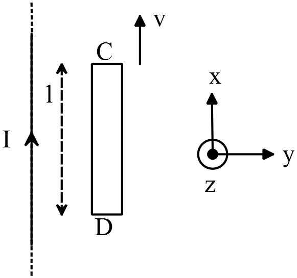
\[V_{CD}=\int^B_A{(\vec{v}\times \vec{B}).d\vec{l}}=\int^B_A{bv\left(-\hat{j}\right).dx\ \hat{i}}=0\]
the potential difference between two points is independent of the path between them (because the electric force is conservative). thus
\[V_{CA}=V_{CE}+V_{EA}\]
\[V_{CE}=0\ same\ reason\ as\ above\to V_{CA}=V_{EA}=-\frac{{\mu }_0Iv}{2\pi }{\mathrm{ln} \frac{d+w}{w}\ }\]
In this part, we have a rode $AE$ with length $w$ instead of $2w$. So we have used the result (a) with substituting w 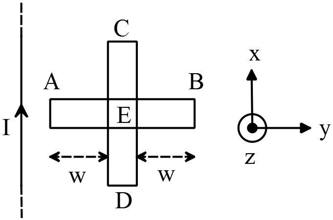 instead of 2w.
Two current loops with equal currents $I$ (both oriented in the same direction) and radii $R$ separated by a long distance $L$ as shown in the figure. $L$ is much larger than $R$.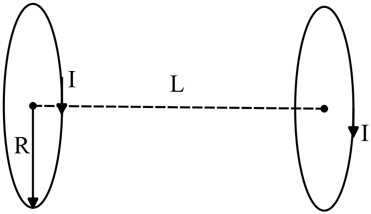
(a) Find the magnetic moments of both current loops.
(b) Find the magnetic field generated by the loop on the left at the center of the other loop on the right.
(c) Show that, in order to separate these loops infinitely far apart, one has to do a positive work given by
\[W={\mu }_0\frac{{\vec{\mu }}_1.{\vec{\mu }}_2}{2\pi {\left(L^2+R^2\right)}^{\frac{3}{2}}}\]
(a) The magnetic moment of a current carrying loop with area $A$ is defined by $\vec{\mu }=IA\hat{n}$ where $\hat{n}$ is the unit vector perpendicular to the plane of the loop. In this case, the both loops have the same area and currents so
\[{\vec{\mu }}_L=IA\hat{n}=I\pi R^2\hat{z}={\vec{\mu }}_R\]
$L$ and $R$ stands for the left and right loops.
(b) The $B$-field of a circular loop (magnetic dipole) with radius $R$ at a point $z$ on the axes of dipole is given by the following relation
\[\vec{B}={\mu }_0\frac{IR^2\hat{n}}{2{\left(L^2+R^2\right)}^{\frac{3}{2}}}\]
So the magnetic field of the left loop at the location of the right loop is
\[{\vec{B}}_L={\mu }_0\frac{IR^2\hat{n}}{2{\left(L^2+R^2\right)}^{\frac{3}{2}}}\xrightarrow{L\gg R}\frac{{\mu }_0}{2\pi }\frac{\vec{{\mu }_1}}{L^3}\]
(c) The total potential energy of this system is : $U=-{\vec{\mu }}_2.{\vec{B}}_1$ or $U=-{\vec{\mu }}_1.{\vec{B}}_2$ So
$U=-{\vec{\mu }}_R.{\vec{B}}_L=-\frac{{\mu }_0}{2\pi }\frac{{\vec{\mu }}_L.{\vec{\mu }}_R}{L^3}<0$, since ${\vec{\mu }}_1={\vec{\mu }}_2$ therefore$=-\frac{{\mu }_0}{2\pi }\frac{{\left|{\mu }_1\right|}^2}{L^3}<0$ .
To separate the loops one has to do work against the potential energy of the system such that the potential energy goes to zero. Hence the work done is:
\[W=-U=\frac{{\mu }_0}{2\pi }\frac{{\left|{\mu }_1\right|}^2}{L^3}>0\]
Consider an infinite cylindrical wire of radius $a$ centered along the $z$ axis with current density $\vec{J}=\hat{z}J_0$, where $J_0$ is a constant which is known.
(a) Draw the direction of the magnetic field vector inside and outside of the wire. (No calculation is required for this part)
(b) Determine the total current that passes through this wire.
(c) What is the strength of the magnetic field inside the wire.(as a function of the radial distance $r$ from the wire axis)
(d) What is the strength of the magnetic field outside the wire?.(as a function of the radial distance $r$ from the wire axis)
(a) The direction of the magnetic field of a straight current carrying wire is 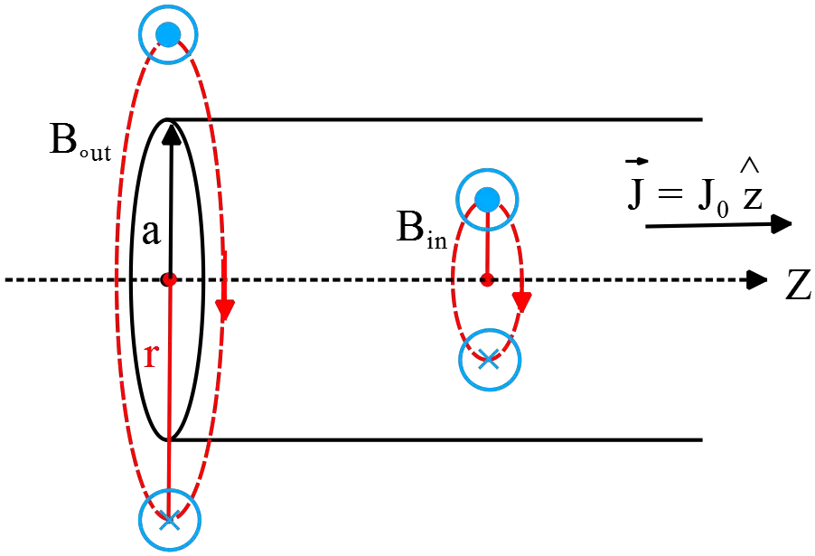 determined by the right hand rule. Point your thumb in direction of the current then the direction that the fingers curl, is direction of the magnetic field.
(b) The current through a surface is defined as the flux of the current density vector $\vec{J}$ that passes through this surface that is $I=\int{\vec{J}.\hat{n}\ dA}=\int{J_0\hat{z}.\hat{z}\ dA}=\pi a^2J_0$, where $\hat{n}$ is the unit vector perpendicular to the surface and $\int{dA}$ is the cross sectional area of the wire.
Note: $=\int{J_0\hat{z}.(\hat{z}dA_1+\hat{r}dA_2)}$ , where $dA_1$ is the bottom and $dA_2$ lateral surface of the cylinder.(in cylindrical coordinate)
(c) From Ampere's law $\oint_C{\vec{B}.d\vec{l}}={\mu }_0I_{enc}$
\[r<R\ ,\ \oint_C{\vec{B}.d\vec{l}}={\mu }_0I_{enc}\to B_{in}\left(2\pi r\right)={\mu }_0\int{J_0\hat{z}.\hat{z}dA}={\mu }_0J_0\pi r^2\]
\[\therefore \ B_{in}=\frac{{\mu }_0J_0}{2r}\]
(d) $r>R,\ \ \ \ \oint_C{\vec{B}.d\vec{l}}={\mu }_0I_{enc}\to B_{out}\left(2\pi r\right)={\mu }_0J_0\pi a^2\to B_{out}=\frac{{\mu }_0J_0}{2r}a^2$
Now express the total current through the wire in terms of initial current density $I_{out}=\int{\vec{J}.\hat{n}dA}=J_0\int{\hat{z}.\hat{z}dA_{total}}=J_0\pi a^2$ , where $dA_{total}$ is the total cross section of the wire.
\[so\ ,\ \ J_0a^2=\frac{I}{\pi }\]
Substituting the $I/\pi $ for $J_0a^2$ in the magnetic field of outside, we obtain
\[B_{out}=\frac{{\mu }_0I}{2\pi r}\]
A current $I_0$ is present in the two circularly arced wire segments of radius $R$ depicted below as thick black lines. One are subtends an angle of $\pi /2$, and the other subtends an angle of $\pi /4$. The lead wires point radially 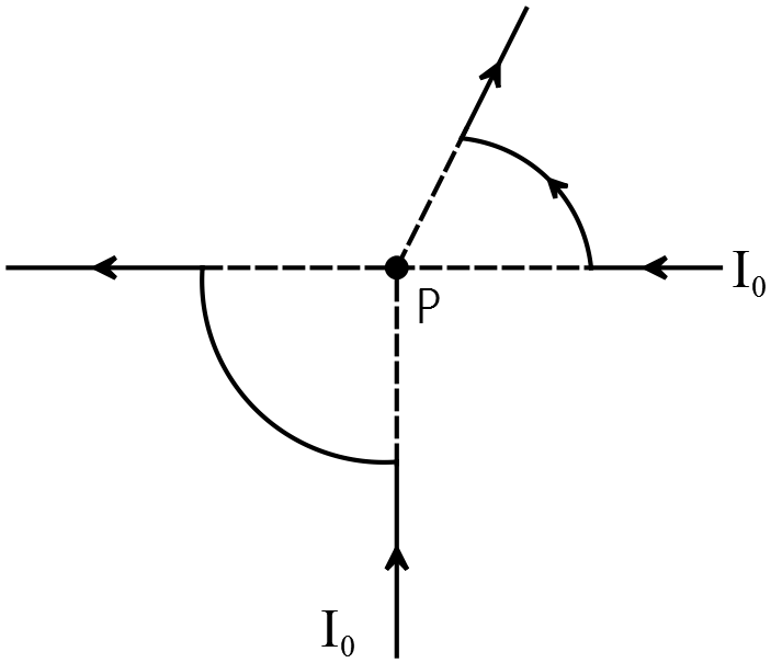 outward from point $P$, the location of the center of the two arced wire segments. Derive from the Bio-Savart law the magnitude and direction of the magnetic field at the point $P$.
The magnetic field $d\vec{B}$ produced by a current element $Id\vec{l}$ at distance $r$ from it is given by the Bio-Savart law as
\[d\vec{B}=\frac{{\mu }_0}{4\pi }\frac{Id\vec{l}\times \hat{r}}{r^2}\]
For example, the magnetic field due to a counter clockwise current loop at the center of the circle is found as
\[\vec{B}=\frac{{\mu }_0}{4\pi }\frac{I}{R^2}\int^{2\pi }_0{\underbrace{\left(Rd\theta \right)\hat{\theta }}_{d\vec{l}}\times \hat{r}}=\frac{{\mu }_0I}{2R}(-\hat{k})\]
Where we have used the polar coordinate and $\hat{\theta }\times \hat{r}=-\hat{k}$. That is the magnetic field is into the page. 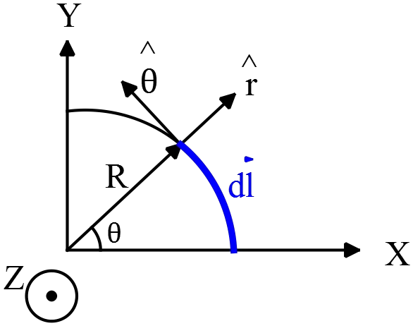
Now first find the magnetic fields due to each of the wire segments at the point $P$. The resultant magnetic field at point $P$ is the vector sum of these fields.
The magnetic fields due to the straight segments of the wire at the point $P$ are zero since the current element and radial direction $\hat{r}$ from the $Id\vec{l}$ to the field point $P$ are parallel and thus their cross product is zero. The magnitude of the magnetic fields due to the arc segments are found as follows
\[B_{arc}=\frac{{\mu }_0}{4\pi }\int^{\theta }_0{\frac{IRd\theta }{R^2}}=\frac{{\mu }_0}{4\pi }\frac{I\theta }{R}\]
Therefore, the magnetic field of the $\pi /2\ $arc at the center of arc i.e. $P$ is $B_{\frac{\pi }{2}}=\frac{{\mu }_0I}{8R}$. Using the right hand rule (put your thumb in direction of the loop, the direction of the rotation of the fingers indicates the direction of the magnetic field at that point), we can see that the direction of the $B_{\frac{\pi }{2}}$ is into the page i.e. ${\vec{B}}_{\frac{\pi }{2}}=\frac{{\mu }_0I}{8R}\left(-\hat{k}\right)$. Similarly, for the $\pi /4\ $ segment we have $B_{\frac{\pi }{4}}=\frac{{\mu }_0I}{16R}\left(+\hat{k}\right)$. Thus, the net magnetic field at the point $P$ is
\[{\vec{B}}_P={\vec{B}}_{\frac{\pi }{2}}+{\vec{B}}_{\frac{\pi }{4}}=\frac{{\mu }_0I}{8R}\left(-\hat{k}\right)+\frac{{\mu }_0I}{16R}\left(+\hat{k}\right)=\frac{{\mu }_0I}{16R}(-\hat{k})\]
So the net magnetic field points into the plane of the paper.
A solenoid with $N$ turns, length $l$ and radius $R$ has a current $I=I_0(1+t/\tau )$, where $\tau $ and $I_0$ are both positive constants and $t$ is time.
(a) Derive an expression for the magnetic field inside the solenoid at a radius of $r$ where $r<R$ at time $t=0$.
(b) Draw the direction of the magnetic field inside the solenoid at time $t=0$ on the diagram above which depicts a cross sectional view of the solenoid.
(c) What is the magnitude of the electric field at radius $r<R$ inside the same solenoid at some arbitrary time $t>0$?
(d) Draw the direction of the electric field at point $P$ (at radius $r$) on the diagram below depicting a bottom view of a solenoid with the current moving clockwise.
(a) Ampere's law states that the line integral $\oint_C{\vec{B}.d\vec{l}}$ 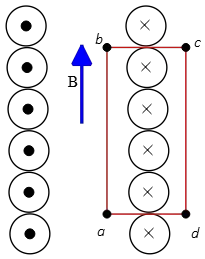 around a closed curve $C$ (Amperian loop) is equals to the current passes through any surface bounded by $C$ times ${\mu }_0$ i.e.
\[\oint_C{\vec{B}.d\vec{l}}={\mu }_0I_C\]
Where $I_c$ is the net current through any surface $S$ bounded by the curve $C$. Therefore, first draw an Amperian loop as shown in the figure, then calculate the line integral around it to find the magnetic field inside the solenoid. If the length of solenoid is long in comparison with the cross sectional diameter then $B_{out}\sim \ 0$. So
\[\oint_C{\vec{B}.d\vec{l}}=\int^b_a{{\vec{B}}_{in}.d\vec{l}}+\underbrace{\int^c_b{{\vec{B}}^{'}.d\vec{l}}}_{0}+\underbrace{\int^d_c{{\vec{B}}_{out}.d\vec{l}}}_{0}+\underbrace{\int^a_d{{\vec{B}}^{'}.d\vec{l}}}_{0}\]
Along sides $bc$ and $da$ the magnetic field of the solenoid ${\vec{B}}^{'}$ is perpendicular to the path and so $\vec{B^{'}}.d\vec{l}=0$. But along $ab$, $B_{in}$ is parallel to the path. In the length $L$ there are $N$ turns that each of which passes once the current $I_0$at time $t=0$ so the total current through the rectangle is $I_C=NI_0$, therefore the Ampere's law is
\[\oint_C{\vec{B}.d\vec{l}}=B_{in}L={\mu }_0NI_0\Rightarrow B_{in}={\mu }_0\frac{N}{L}I_0\]
(b) Using the right hand rule, we obtain the direction of the magnetic field inside the solenoid as shown in the sketch.
(c) Faraday's law states that a time varying magnetic flux produces an induced emf (voltage) $\mathcal{E}$ and an induced current in any closed loop. In the mathematical form this law is
\[\mathcal{E}=-\frac{d{\mathrm{\Phi }}_B}{dt}=-\frac{d}{dt}\int{\vec{B}.\hat{n}dA}\]
Let us imagine that we have an imaginary circular loop of radius $r$ and perpendicular to the solenoid axis. There is a time varying magnetic field $B$ passing normally through the cross sectional area of the loop. So the flux change inside the loop induces a voltage that is related to the magnitude of the induced electric field by $\left|E\right|=\left|-d\mathcal{E}/d\ell \right|$, where $\ell $ is the circumference of the loop. Thus using the Faraday's law, we obtain
\[\left|\mathcal{E}\right|=\left|-\frac{d{\mathrm{\Phi }}_B}{dt}\right|\to E\left(2\pi r\right)=\frac{d}{dt}\left(B_{in}\left(t\right)\pi r^2\right)\]
\[\left|E_{in}\right|=\frac{1}{2\pi r}\frac{d}{dt}\left({\mu }_0\frac{N}{L}I\left(t\right)\right)\left(\pi r^2\right)=\frac{r}{2}\frac{{\mu }_0N}{L}\frac{I_0}{\tau }\]
(d) Using the Lenz's law, we can determine the direction of induced current in an imaginary closed loop shown in the figure. Lenz's law: the induced current in a loop is in the direction that the magnetic field produced by it opposes the change in the magnetic flux through the area enclosed by the loop. Since, in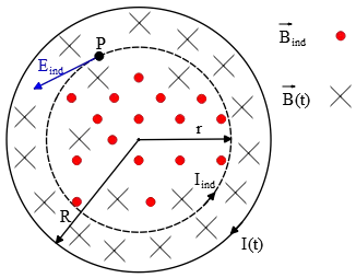 this case, we have a time varying current ($I(t)$) so the magnetic field inside the solenoid (or any closed loop) is increasing with time. By Lenz's law, the induced current ($I_{ind}$) must be counter clockwise to create an induced magnetic field in opposite direction of the magnetic field of the solenoid. Since the electric field drives the current, hence the induced electric field $\left|E_{in}\right|$ would be tangential and counter clockwise.
A solenoid has $N$ turns, a radius $R_{sol}$, a total length $L$ and a current $I_{sol}$. The solenoid depicted below is a cross sectional view.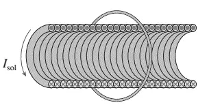
(a) Draw the direction of the magnetic field inside the solenoid.
(b) What is the magnetic flux produced by the solenoid on a concentric circular loop of radius $a$?
(c) If $I_{sol}$ is decreasing, what is the direction of the induced current in the loop?
(a) Use the right hand rule as follows to find the direction of the magnetic field of the solenoid. Point your right thumb along the $I_{sol}$ and let your fingers curl through the center of the loop then your fingers pointing in the direction of the $B_{sol}$ that in this case is to the left.
(b) Using the Ampere's law we can obtain the magnetic field inside the solenoid as $B_{in}={\mu }_0\frac{N}{L}I_{sol}$. By definition, the magnetic flux passing through any surface $A$ is ${\mathrm{\Phi }}_M=\vec{B}.\hat{n}A$ where $\hat{n}$ is the unit vector normal to the surface. Since the magnetic field outside an ideal solenoid is zero so the area of the loop is not $\pi a^2$ but $\pi R^2_{sol}$. Thus we obtain
\[{\mathrm{\Phi }}_M=B_{in}\left(\pi R^2_{sol}\right)={\mu }_0\frac{N}{L}I_{sol}\left(\pi R^2_{sol}\right)\]
(c) Since the $I_{sol}$ is decreasing, the magnetic flux through the loop decreases. By Lenz's law, the direction of the induced current must be such that the magnetic field created by it opposes the decreasing original flux through the loop. So the induced current must be in the same direction as $I_{sol}$.
A particle with charge $q$ and mass $m$ is moving in a circular path perpendicular to a constant magnetic field. The particle takes a time $T$ to complete one revolution. Determine the magnitude of the magnetic field in term of $q,m$ and $T$.
A particle moves in a circular path experiences a centripetal force. This force provided by the moving of the charged particle in a magnetic field. Applying Newton's second law and Lorentz force formulae for the magnetic field, we obtain
\[F_r=ma_r=mr{\omega }^2\Rightarrow F_r=mr{\left(\frac{2\pi }{T}\right)}^2\]
Where $T$ is the period of the motion and is related to the angular velocity by $\omega =2\pi /T$
\[{\vec{F}}_m=q\vec{v}\times \vec{B}\]
Since the velocity of the particle perpendicular to the external magnetic field, 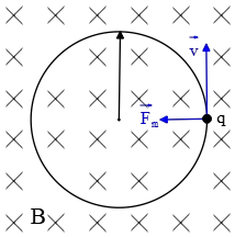 the magnitude of the magnetic force is $F_m=qvB$. The velocity of a particle in a circular path is related to the angular velocity by $v=r\omega $.
\[F_r=F_m\]
\[qvB=mr{\left(\frac{2\pi }{T}\right)}^2\to q\left(\frac{r2\pi }{T}\right)B=mr{\left(\frac{2\pi }{T}\right)}^2\]
\[\Rightarrow B=\frac{2\pi }{T}\frac{m}{q}\]
Note: this particle must be in clockwise direction to the force exerted on it by magnetic field provides the centripetal acceleration. Using the right hand rule, points your right hand fingers in the direction of the velocity of the particle such that your palm to be in direction of the magnetic field, your thumb points to the magnetic field, we find the correct direction of the particle.
Three very long current carrying wires are arranged to form an equilateral triangle with side $R$, as shown in the figure below. The bottom two wires 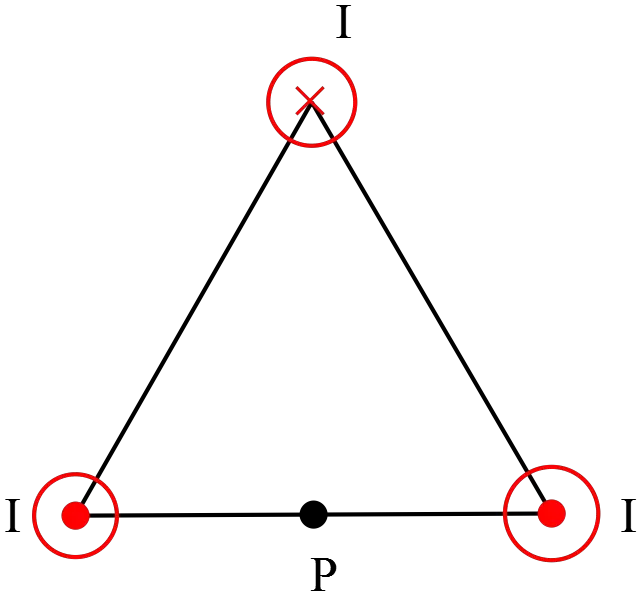 carry current $I$ out of the page, and the top wire carries current $I$ into the page.
(a) Determine the magnetic field at the location of top wire due to the bottom two wires.
(b) Determine the force per unit length on the top wire due to the bottom wire.
(c) Determine the magnetic field at the location of the lower left wire due to the other two.
(d) Determine the magnetic field at the point $P$ midway between the lower two wires.
(e) A particle with charge $+q$ is released from rest at point $P$. Determine the force on this particle due to the magnetic field immediately after it is released.
(f) A particle with charge $+q$ is released with initial velocity in the $x$ direction, $\vec{v}=v_0\hat{j}$. Determine the force on this particle due to the magnetic field immediately after it is released.
(a) The magnetic field due to a long, straight wire which carries current $I$at 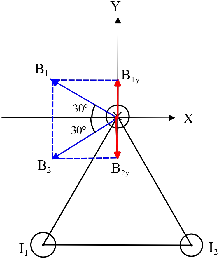 distance $r$ around it form concentric circles which itsmagnitude is given by the Ampere's law as follows
\[B=\frac{{\mu }_0I}{2\pi r}\]
The direction of the magnetic field is in the plane which is perpendicular to the wire and is tangent to the concentric circles. Point your right thumb along the current, the direction of the curling your fingers around the wire represents the direction of the magnetic field (right hand rule).
The magnetic field at the location of the top wire has two contributions, ${\vec{B}}_1$ and ${\vec{B}}_2$. The directions of ${\vec{B}}_1$ and ${\vec{B}}_2$ at the top wire are perpendicular to the line from wires $1$ and $2$ to the top wire $3$.
From the figure, it is clear that the $y$ components cancel each other and the $x$ components add. Therefore,
\begin{align*} B_{tot}\left(3\right) &=B_{1x}+B_{2x}=\left|{\vec{B}}_1\right|{\mathrm{cos} 30{}^\circ \ }+\left|{\vec{B}}_2\right|{\mathrm{cos} 30{}^\circ \ }=2\left|B_{1,2}\right|{\mathrm{cos} 30{}^\circ \ }\\ &=2\frac{{\mu }_0I}{2\pi R}{\mathrm{cos} 30{}^\circ \ }=\frac{\sqrt{3}}{2}\frac{{\mu }_0I}{\pi R} \end{align*}
In above, we have used the fact that the $\left|{\vec{B}}_1\right|=\left|{\vec{B}}_2\right|$. Thus the total magnetic field at location of top wire due to the bottom wires is in direction of $-\hat{i}$ with the magnitude above.
(b) The force per unit length exerted on a straight wire carrying current $I$ in presence of a uniform external magnetic field $\vec{B}$ is given by $\vec{F}=i\vec{l}\times \vec{B}$. This force is perpendicular to both $\vec{B}$ and the vector $\vec{l}$, which points in the direction of the current.
Therefore, the magnetic force that the top wire experiences due to the presence of the bottom wires is calculated as follows
\[{\vec{F}}_3=I{\vec{l}}_3\times {\vec{B}}_{1,2}=I\ L_3\left(-\hat{k}\right)\times B_{1,2}\left(-\hat{i}\right)=IL_3\left|B_{1,2}\right|\underbrace{\left(\hat{k}\times \hat{i}\right)}_{\hat{j}}\]
\[\Rightarrow \frac{{\vec{F}}_3}{L_3}=\frac{\sqrt{3}}{2}\frac{{\mu }_0I^2}{\pi R}\hat{j}\]
(c) Similar to the part (a), 
\[{\vec{B}}_2=\frac{{\mu }_0I}{2\pi R}\left(-\hat{j}\right)\]
\[{\vec{B}}_3=\frac{{\mu }_0I}{2\pi R}\left({\mathrm{cos} 30{}^\circ \ }\left(-\hat{i}\right)+{\mathrm{sin} 30{}^\circ \ }\hat{j}\right)\]
The total magnetic field at location of wire $1$ is determined by the superposition principle as
\[{\vec{B}}_{tot}(1)={\vec{B}}_2+{\vec{B}}_3\]
\[=\frac{{\mu }_0I}{2\pi R}\left(-\hat{j}\right)+\frac{{\mu }_0I}{2\pi R}\left({\mathrm{cos} 30{}^\circ \ }\left(-\hat{i}\right)+{\mathrm{sin} 30{}^\circ \ }\hat{j}\right)\]
\[=\frac{{\mu }_0I}{2\pi R}\left({\mathrm{cos} 30{}^\circ \ }\left(-\hat{i}\right)+\left({\mathrm{sin} 30{}^\circ \ }-1\right)\hat{j}\right)\]
\[\Rightarrow {\vec{B}}_{tot}(1)=-\frac{{\mu }_0I}{2\pi R}\left(\frac{\sqrt{3}}{2}\hat{i}+\frac{1}{2}\hat{j}\right)\]
(d) Using the right hand rule find the directions of the magnetic fields due to 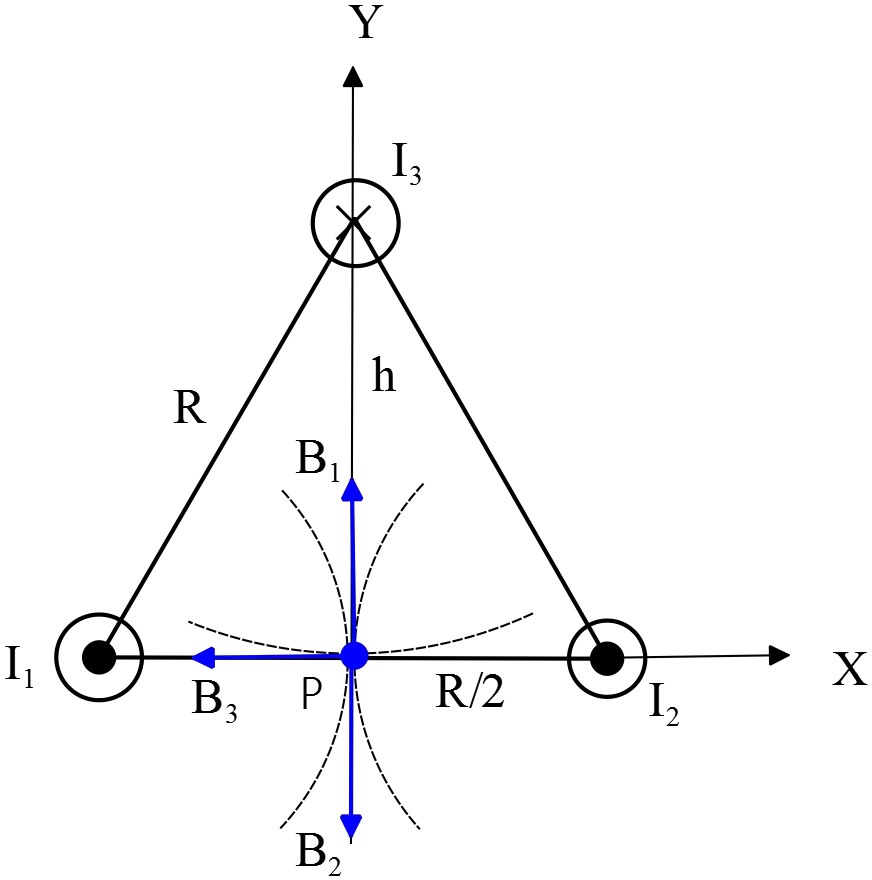 the wires at the point $P$, then use the superposition principle to determine the total magnetic field at that point. As shown in the figure, the two contribution $B_1$ and $B_2$ cancel each other, so the only remaining field is $B_3$ due to the wire $3$ which is in the $-\hat{i}$ direction.
\[{\vec{B}}_{tot}\left(P\right)={\vec{B}}_3=\frac{{\mu }_0I}{2\pi h}\left(-\hat{i}\right)\]
Where $h^2+{\left(\frac{R}{2}\right)}^2=R^2$ (from Pythagoras theorem).
\[\Rightarrow h=\sqrt{R^2-\left(\frac{R^2}{4}\right)}=\frac{\sqrt{3}}{2}R\]
\[\therefore {\vec{B}}_{tot}\left(P\right)=\frac{{\mu }_0I}{2\pi \left(\frac{\sqrt{3}}{2}R\right)}=\frac{{\mu }_0I}{\sqrt{3}\pi R}\left(-\hat{i}\right)\]
(e) A moving charge $q$ with velocity $\vec{v}$ in an external magnetic field $\vec{B}$ experiences the following magnetic force $\vec{F}=q\vec{v}\times \vec{B}$. This force is perpendicular to both velocity and magnetic field and its direction is found by the right hand rule. Therefore,
\[{\vec{F}}_P=q\vec{v}\times \vec{B}=0\]
Since we want the force acted on the particle immediately after releasing from rest, so its initial velocity is zero i.e. $\vec{v}=0$.
(f) Now in this part, the initial velocity is $\vec{v}=v_0\hat{j}$, so the initial force acted on the particle immediately after releasing is
\[\vec{F}=q\vec{v}\times \vec{B}=qv_0\hat{j}\times \left|{\vec{B}}_{tot}\left(P\right)\right|\left(-\hat{i}\right)\]
\[=-qv_0\left|{\vec{B}}_{tot}\left(P\right)\right|\underbrace{\left(\hat{j}\times \hat{i}\right)}_{-\hat{k}}\]
By substituting $\left|{\vec{B}}_{tot}\left(P\right)\right|$ from part (d) into above, we get
\[\Rightarrow {\vec{F}}_P=\frac{{\mu }_0Iqv_0}{\sqrt{3}\pi R}\hat{k}\]
We can explicitly show the direction of the force above, by using the right hand rule. Point your right hand fingers along the velocity and curl them in direction of the magnetic field. Your thumb shows the direction of the magnetic force acted.
The region of space $x>0$ is permeated by a uniform magnetic field $\vec{B}=B\hat{k}$pointing in the $z$ direction; the field is zero in the region $x\ <\ 0$. A particle of charge $q$ and velocity $\vec{v}=v\,\hat{i}$ enters the region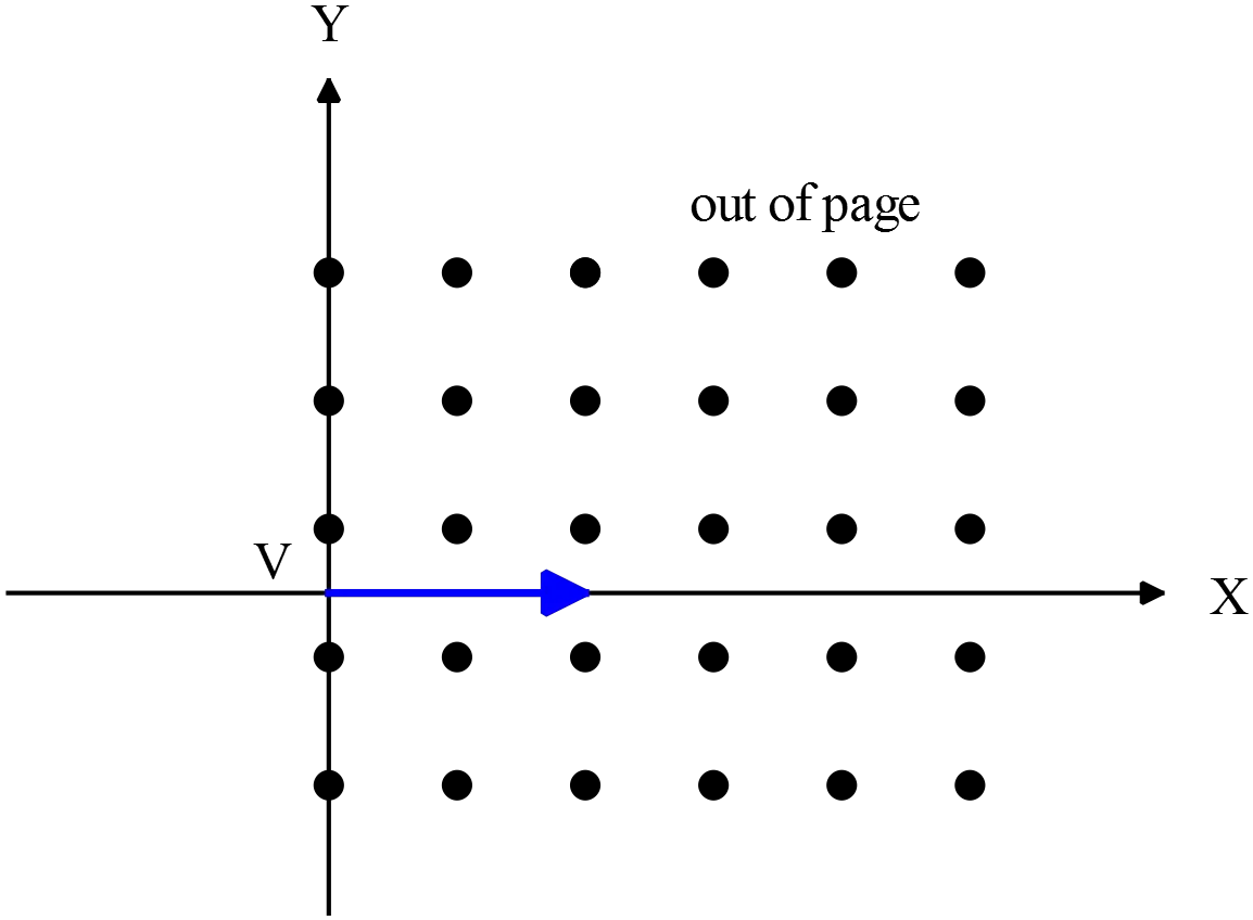 of non-zero field at the point with $(x,\ y,\ z)$ coordinates $(0,\ 0,\ 0)$. What are the coordinates of the point where the particle exits the region of nonzero field?
A moving charge $q$ with velocity $\vec{v}$ in an external magnetic field $\vec{B}$ experiences a force as $\vec{F}=q\vec{v}\times \vec{B}$. Since $F$ is always perpendicular to the magnetic field $B$, it does not work on the charge and cannot change the magnitude of the velocity of the particle but this force can change the direction of the moving particle. In the special case where the velocity of the charged particle is perpendicular to the magnetic field, the particle moves in a circular path. We know, a particle in a circular orbit experiences centripetal force. In this case, this force is provided by the magnetic force. Use Newton's second law to find the radius of the orbit as follows \[\left\{ \begin{array}{rcl} F_r & = &\frac{mv^2}{r} \\ F_B & = &qvB \end{array}\right.\Rightarrow F_r=F_B\] \[\Rightarrow \frac{mv^2}{r}=qvB\Rightarrow r=\frac{mv}{qB}\] $r$ is the radius of the particle in this configuration.If the fingers of the right hand are in the direction of the velocity $\vec{v}$ so that they can be turned toward the $\vec{B}$, the thumb points in the direction of the force $\vec{F}$ (right-hand rule). Using this rule, at the moment that the particle enters in the non-zero region of $\vec{B}$, the force is in the direction of the $-y$ axis. Therefore, the exit coordinate of the particle is $(0,-2r,0)$.
\[(0,-\frac{2mv}{qB},0)\]
The figure shows a square $\mathrm{(10\ cm\ \times \ 10\ cm)}$, $10$-turn coil of wire, which carries a current of $1.0\ A$. The coil is hinged along one side, as 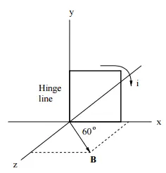 shown in the figure, and is mounted in the $x\ -\ y$ plane, at $60{}^\circ $ to the direction of a uniform magnetic field of magnitude $\mathrm{2.0\ T}$. What is the magnitude of the torque acting on the coil (about the hinge line)?
A current loop with the magnetic moment $\vec{\mu }$ in an external field $\vec{B}$ experiences a torque $\vec{\mu }\times \vec{B}$ which is perpendicular to both of them. This torque tends to twist the loop in the same direction of the magnetic field. The magnetic moment defines as
\[\vec{\mu }=NIA\hat{n}\]
Where $\hat{n}$ is the unit vector normal to the surface encompasses by the current loop and $N$ is the number of the loops. $A$ is also the area of the surface.
The magnetic moment of this loop is in the $-z$ axis direction (curl your right hand fingers around the direction of the current in the loop, your thumb points to the direction of the $\vec{\mu }$ ). Decompose the vector field $\vec{B}$ into the $x$ and $z$ components as
\[\vec{B}=\left|\vec{B}\right|{\cos 60{}^\circ \ }\hat{x}+\left|\vec{B}\right|{\sin 60{}^\circ \ }\hat{z}\]
Thus the cross product of $\vec{\mu }$ and $\vec{B}$ becomes
\begin{align*}\vec{\tau }&=\vec{\mu }\times \vec B\\ &=NIA\left(-\hat{z}\right)\times \left(\left|\vec{B}\right|{\cos 60{}^\circ \ }\hat{x}+\left|\vec{B}\right|{\sin 60{}^\circ \ }\hat{z}\right)\\ &=-NIA\left|\vec{B}\right|{\cos 60{}^\circ \ }\underbrace{\left(\hat{z}\times \hat{x}\right)}_{\hat{y}} \end{align*}
\[\Rightarrow \ \vec{\tau }=-NIA\left|\vec{B}\right|{\cos 60{}^\circ \ }\hat{y}\]
Substituting the given data into the above, we obtain
\[\vec{\tau }=-\left(10\right)\left(1\mathrm{A}\right)\left(100\times {10}^{-4}\,{\mathrm{m}}^{\mathrm{2}}\right)\left(2\,\mathrm{T}\right)\left(\frac{\mathrm{1}}{\mathrm{2}}\right)\mathrm{=0.1}\left(\hat{y}\right)\mathrm{N.m}\]
As shown in the figure, a long straight wire carries a current of $\mathrm{30\ A}$ and is co-planar with a square loop of side $\mathrm{10\ cm}$ which carries a 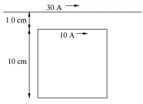 current of $\mathrm{10\ A}$. If the distance between the wire and the nearest side of the loop is $\mathrm{1.0\ cm}$, what is the magnitude and direction of the net force on the loop? Recall that ${\mu }_0=4\pi \times {10}^{-7}\mathrm{T.m/A}$
If a current carrying wire inserted into an external magnetic field, it 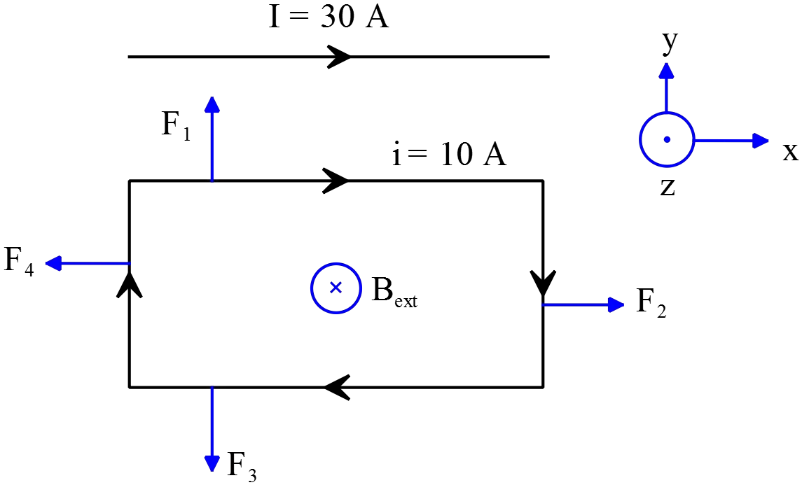 experiences a magnetic force that is defined by the $\vec{F}=i\vec{l}\times \vec{B}$.
In this problem, a current rectangular loop is into the magnetic field $B_{ext}$ that is produced by the current carrying straight wire $I$ so we must find the magnetic force acting on each of sides of the loop. Recall that the magnetic field of a straight current carrying wire at distance $r$ around it is
\[B=\frac{{\mu }_0I}{2\pi r}=\frac{\left(4\pi \times {10}^{-7}\right)\left(30\right)}{2\pi r}=6\times {10}^{-6}\frac{1}{r}\]
In this case $r$ is the distance of each sides of loop from the wire.
\[{\vec{F}}_1=i{\vec{l}}_1\times {\vec{B}}_{ext}=10\left(0.1\right)\hat{x}\times \frac{6\times {10}^{-6}}{0.01\ \mathrm{m}}\left(-\hat{z}\right)=-(6\times {10}^{-4})\underbrace{\left(\hat{x}\times \hat{z}\right)}_{-\hat{y}}=(6\times {10}^{-4})\ \mathrm{N\ }\hat{y}\]
${\vec{F}}_1$ is the force acting on the upper side of the loop by the wire.
\[{\vec{F}}_2=i{\vec{l}}_2\times {\vec{B}}_{ext}=10\left(0.1\right)\left(-\hat{y}\right)\times \frac{6\times {10}^{-6}}{r}\left(-\hat{z}\right)=\frac{6\times {10}^{-6}}{r}\underbrace{\left(\hat{y}\times \hat{z}\right)}_{\hat{x}}=\frac{6\times {10}^{-6}}{r}\mathrm{N\ }\hat{\mathrm{x}}\]
\[{\vec{F}}_3=i{\vec{l}}_3\times {\vec{B}}_{ext}=10\left(0.1\right)\left(-\hat{x}\right)\times \left(\frac{6\times {10}^{-6}}{10.1\times {10}^{-2}\mathrm{m}}\right)\left(-\hat{z}\right)=(0.6\times {10}^{-4})\underbrace{\left(\hat{x}\times \hat{z}\right)}_{-\hat{y}}=-(0.6\times {10}^{-4})\mathrm{N\ }\hat{\mathrm{y}}\]
\[{\vec{F}}_4=i{\vec{l}}_4\times {\vec{B}}_{ext}=10\left(0.1\right)\hat{y}\times \left(\frac{6\times {10}^{-6}}{r}\right)\left(-\hat{z}\right)=-\frac{6\times {10}^{-6}}{r}\underbrace{\left(\hat{y}\times \hat{z}\right)}_{+\hat{x}}=-\frac{6\times {10}^{-6}}{r}\mathrm{N\ }\hat{\mathrm{x}}\]
Use the superposition principle, vector addition of each of the forces, to find the net force acting on the loop.
\[{\vec{F}}_{net}={\vec{F}}_1+{\vec{F}}_2+{\vec{F}}_3+{\vec{F}}_4=\left(6-0.6\right)\times {10}^{-4}\mathrm{N\ }\hat{\mathrm{y}}=5.4\times {10}^{-4}\mathrm{N\ }\hat{\mathrm{y}}\]
The forces $F_2$ and $F_4$ are equal but in opposite direction so they cancel each other.
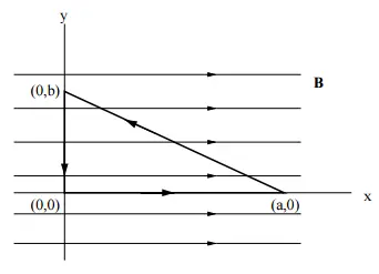
A uniform magnetic field $\vec{B}=B_0\hat{i}$ points in the $x$-direction. What is the value of the integral $\oint{\vec{B}.d\vec{s}}$ around the closed triangular path shown in the figure?
The integral above is similar to the Ampere's law. This law states that the linear integral of magnetic field $\vec{B}$ around a closed curve $C$ is proportional to the current passing through the surface bounded by the curve $C$. In the mathematical language
\[\oint_C{\vec{B}.d\vec{s}}={\mu }_0I_{enc}\]
Since there is no current passing through the triangular path shown, the integral above must be equal to zero!
\[I_{enc}=0\Rightarrow \ \oint_C{\vec{B}.d\vec{s}}=0\]
We can show explicitly the result above.
The dot product of vertical path and magnetic field is zero, since the angle between them is $90{}^\circ $. For the horizontal path, we have
\[\int^a_0{\vec{B}.d\vec{s}}=B\int^a_0{{\mathrm{cos} 0{}^\circ \ }dx}=Ba\]
The incline path have two components, the dot product of the its vertical component and $\vec{B}$ is zero, so the integral along its horizontal component is found as
\[\int^0_a{\vec{B}.d\vec{s}}=B\int^0_a{{\mathrm{cos} 180{}^\circ \ }dx}=-Ba\]
Thus, the linear integral $\oint{\vec{B}.d\vec{s}}$ is sum of the integrals above,
\[\oint{\vec{B}.d\vec{s}}=\int^a_0{\vec{B}.d\vec{x}}+\int^{0,b}_{a,0}{\vec{B}.d\vec{s}}+\int^0_b{\vec{B}.d\vec{y}}\]
\[=Ba-Ba=0\]
A circular-shaped circuit of radius $r$, containing a resistance $R$ and capacitance $C$, is situated with its plane perpendicular to the spatially uniform magnetic field within which it is immersed. The magnetic field is directed into the page as shown. Starting at time $t\ =\ 0$, the voltage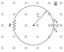 difference $V_{ba}=V_b\ -V_a$ across the capacitor plates is observed to increase with time according to $V_{ba}=V_0\left(1\ -\ e^{-\frac{t}{\tau }}\right)$ where $V_0$ and $\tau $ are positive constants. Determine $dB/dt$, the rate at which the magnetic field magnitude changes with time. Is $B$ becoming larger or smaller as time increases?
The changing magnetic field creates an induced emf in the loop. Applying the Kirchhoff's loop rule, the sum of the potential differences around a closed loop must be zero, and considering the induced emf $\mathcal{E}$in the circuit, we get
\[\mathcal{E}=\mathrm{\Delta }V_R+\mathrm{\Delta }V_C\to \ \mathcal{E}=\left(-IR\right)+\underbrace{\left(-\frac{Q}{C}\right)}_{V_0\left(1\ -\ e^{-\frac{t}{\tau }}\right)}\]
Since the voltage across the capacitor increases with time, $V_b-V_a>0$, the induced current must be in clockwise direction otherwise the capacitor being completely discharged through the resistor. We know that the potential difference across resistor in the direction of current is $-IR$. From the given voltage across the capacitor and using the definitions of the current $I=dQ/dt$ and capacitance $C=Q/V$ one can derive the current in the loop.
\[I=\frac{dQ}{dt}=\frac{d}{dt}\left(CV\right)=C\frac{dV}{dt}=\frac{CV_0}{\tau }e^{-\frac{t}{\tau }}\]
By substituting the time constant of the $C-R$ circuit $\tau =CR$ into above, we get
\[I=\frac{V_0}{R}e^{-\frac{t}{\tau }}\]
Using Faraday's law, the emf around the loop is equal to the time derivative of the flux $\mathcal{E}=-d\mathrm{\Phi }/dt$, we can rearrange the loop rule as follows
\[-\frac{d\mathrm{\Phi }}{dt}=-\left(\frac{V_0}{R}e^{-\frac{t}{\tau }}\right)R-V_0\left(1-e^{-\frac{t}{\tau }}\right)\to A\frac{dB}{dt}=V_0\]
Since the area of the loop $A=\pi r^2$ is constant, we can factor it out of integral. Consequently, the rate of change of the magnetic field is
\[\frac{dB}{dt}=\frac{V_0}{\pi r^2}\]
As similar reasoning above for the direction of the current in the loop, by Lenz's law this induced current produces a downward flux that strengthen the original flux from the external $B$. So the external magnetic field must be decreasing.
An electron enters a uniform magnetic field at a $45{}^\circ $ angle to the magnetic field $B$. Determine the radius $r$ and pitch $p$ (distance between loops) of the electron's helical path assuming its speed is $3\times {10}^6\mathrm{m/s}$.
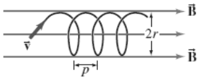
If electron enters with angle $\theta $ into the magnetic field $B$, it moves around a helical path instead of circular path. In this case, we have two motions, one is parallel to the $\vec{B}$ and the other is perpendicular to $\vec{B}$. In the perpendicular case, the electron experiences a centripetal force that is caused by the magnetic force $F_m$. Using the definition of the force acting on a moving charge in the external magnetic field, ${\vec{F}}_m=q\vec{v}\times \vec{B}$, and Newton's second law, we can obtain the radius of the circular path as follows
\[\left|{\vec{F}}_m\right|=qv_{\bot }B\ \ ,\ \ F_r=\frac{mv^2_{\bot }}{r}\]
Where $v_{\bot }=v\,{\mathrm{sin} \theta \ }$ is the perpendicular component of the velocity and $\theta $ is the angle between $\vec{v}$ and $\vec{B}$. Therefore,
\[qv_{\bot }B=\frac{mv^2_{\bot }}{r}\Rightarrow r=\frac{mv_{\bot }}{qB}=\frac{\left(9.11\times {10}^{-31}\right)\left(3\times {10}^6\right){\mathrm{sin} 45{}^\circ \ }}{(1.6\times {10}^{-19})(0.28)}=4.314\times {10}^{-5}\mathrm{\ m}\]
The period of circular motion is defined as
\[T=\frac{L}{v_{\bot }}=\frac{2\pi r}{v_{\bot }}\]
$L=2\pi r$ is the circumference of the circular motion. The distance the electron moves along the magnetic field is called the pitch of the helical path found by $p=v_{\parallel }T$. Thus
\[p=v_{\parallel }T=v_{\parallel }\left(\frac{2\pi r}{v_{\bot }}\right)=\frac{2\pi r\left(v{\mathrm{cos} 45{}^\circ \ }\right)}{v{\mathrm{sin} 45{}^\circ \ }}=2\pi r\,{\mathrm{cot} 45{}^\circ \ }\]
\[=2\pi \left(4.314\times {10}^{-5}\right)=27.10\times {10}^{-5}\mathrm{m}\]
A particle with charge $9.0\ \mathrm{C}$ moving at $\vec{v}=3\ \hat{i}\, \mathrm{m/s}$ enters a magnetic field $\vec{B}=13\ \hat{j}\mathrm{T}$ and an electric field $\vec{E}=21\ \hat{\mathrm{k}}\, \mathrm{N/C}$. find the acceleration of the particle it its mas is $0.00200\ \mathrm{kg}$.
When a moving charge with velocity $\vec{v}$ enters a region of both electric and magnetic fields, it experiences a force called Lorentz force which is calculated by $\vec{F}=q(\vec{E}+\vec{v}\times \vec{B})$. Thus
\[\vec{F}=9\left(21\ \hat{k}+\left(3\hat{i}\times 13\hat{j}\right)\right)=9\left(21+39\right)\hat{k}=540\ \hat{k}\]
Now using Newton's second law, find the acceleration of the charged particle as
\[\vec{a}=\frac{\vec{F}}{m}=\frac{540}{0.002}=270000\ \hat{k}\frac{\mathrm{m}}{\mathrm{s}}\]
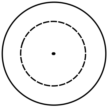
A hollow cylinder with an inner radius of $\mathrm{4.0\ mm}$ and an outer radius of $\mathrm{30\ mm}$ conducts a $\mathrm{3.0\ A}$ current. What is the magnitude of the magnetic field at a point $\mathrm{12\ mm}$ from its center? Assume that the current density is uniform throughout the wire.
Using the Ampere's law, we can find the magnetic field of a highly symmetric configuration such as this case. In the mathematical form is
\[\oint_C{\vec{B}.d\vec{l}}={\mu }_0I_{enc}\]
$C$ is the closed curve which the line integration $\oint $ is performed around it. $I_{enc}$ is also the current passing through the surface bounded by this curve. Let $a=4\ \mathrm{mm}$ and $b=30\ \mathrm{mm}$ be the inner and outer radius of the cylinder, respectively. $r$ is the radius of the contour $C$.
\[\oint_C{\vec{B}.d\vec{l}}={\mu }_0I_{enc}\Rightarrow B\underbrace{\oint_C{dl}}_{2\pi r}={\mu }_0I_{enc}\]
The current through a cross sectional of a wire is defined as the flux of the current density vector $\vec{J}$ through the surface or in mathematical form $J=I/A$. Since the current density is uniform throughout the wire so we have $J_C=J_{cylinder}$. Therefore
\[\frac{I_{enc}}{\pi r^2-\pi a^2}=\frac{I_{tot}}{\pi b^2-\pi a^2}\Rightarrow I_{enc}=\frac{r^2-a^2}{b^2-a^2}I_{tot}\]
Substituting this into the Ampere's law, we obtain the magnetic field inside the wire at the arbitrary radius $r$
\[B=\frac{{\mu }_0}{2\pi r}\frac{r^2-a^2}{b^2-a^2}I_{tot}\]
The given data for this problem are $I_{tot}=3\ \mathrm{A,\ r=12\ mm,\ \ }{\mu}_0=4\pi \times {10}^{-7}$
\[B=\frac{4\pi \times {10}^{-7}}{2\pi \left(12\mathrm{\times }{\mathrm{10}}^{\mathrm{-}\mathrm{3}}\mathrm{m}\right)}\frac{{\left(12\mathrm{mm}\right)}^{\mathrm{2}}-{\left(4\mathrm{mm}\right)}^{\mathrm{2}}}{{\left(30\mathrm{mm}\right)}^{\mathrm{2}}-{\left(4\mathrm{mm}\right)}^{\mathrm{2}}}\left(3\right)=7.23\times {10}^{-6}\]
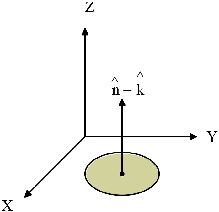
A $\mathrm{10\ m}$ long conductor is formed into a circle in the $\mathrm{xy}$-plane. A uniform magnetic field $\vec{B}=4\hat{i}+19\hat{j}+24\hat{k}\ \mathrm{T}$exists in the area of the conductor. Find the magnetic flux through the looped conductor.
The magnetic flux through a surface $S$ is defined by
\[{\mathrm{\Phi }}_M=\int{\vec{B}.\hat{n}dA}\]
Where $\hat{n}$ is the unit vector normal to the surface $S$ and $dA$ is the area element. Since both $\vec{B}$ and $\vec{A}$ are constant so we can rewrite the above equation as ${\mathrm{\Phi }}_M=\vec{B}.\vec{A}$. therefore,
\[{\mathrm{\Phi }}_M=\left(4\hat{i}+19\hat{j}+24\hat{k}\right).\left(\pi r^2\right)\hat{k}=\pi r^2\left\{4\underbrace{\left(\hat{i}.\hat{k}\right)}_{0}+19\underbrace{\left(\hat{j}.\hat{k}\right)}_{0}+24\underbrace{\left(\hat{k}.\hat{k}\right)}_{1}\right\}\]
\[\Rightarrow \ {\mathrm{\Phi }}_M=24\pi r^2\]
Now we must find the radius of the loop. The circumference of the loop is given $L=10\,\mathrm{m}$, so by using $L=2\pi r$, we can find the radius $r$ as follows
\[r=\frac{L}{2\pi }\]
Substituting this into the ${\mathrm{\Phi }}_M$, we obtain
\[{\mathrm{\Phi }}_M=24\ \pi {\left(\frac{L}{2\pi }\right)}^2=\frac{6}{\pi }L^2=\frac{6}{\pi }{\left(10\right)}^2=191\ \mathrm{T.}{\mathrm{m}}^{\mathrm{2}}\]
The magnetic field strength within a long solenoid is $\mathrm{B=4.0\ t\ T}$, where $t$ is time in seconds. If the radius of the solenoid is $\mathrm{1.0\ cm}$, what is the magnitude of the non-Coulomb force that acts on a $\mathrm{6.0\ C}$ charge a distance $\mathrm{6.0\ cm}$ from the axis of the solenoid?
There is a changing magnetic field and so a changing magnetic flux. According to Faraday's law, this changing flux produces an electric field whose line integral around a closed curve is proportional to the rate of change of the magnetic flux through any surface bounded by this curve. That is
\[\mathcal{E}=\oint_C{\vec{E}.d\vec{l}}=-\frac{d{\mathrm{\Phi }}_M}{dt}=-\frac{d}{dt}\int{\vec{B}.\hat{n}dA}\]
We must find the electric field at radius $r=6\ \mathrm{cm}$. so consider a circular disk of radius $r>R$, and calculate the changing flux passing through the surface bounded by it and the line integral of the electric field as follows
\[\oint_C{\vec{E}.d\vec{l}}=-\frac{d{\mathrm{\Phi }}_M}{dt}=-\frac{d}{dt}\left(\vec{B}.\vec{A}\right)\]
\[E\underbrace{\oint_C{dl}}_{2\pi r}=-A\frac{dB}{dt}=-\pi R^2\underbrace{\frac{d}{dt}\left(4t\right)}_{4}\]
In above $A=\pi R^2$ is the cross sectional area of the solenoid. The total flux passes through this area so we must not substitute the area of the surface bounded by the curve $C$.The electric field is constant everywhere on the circular disk so we can factor it out of the integral. The line integral $\oint_C{dl}$ is the circumference of the loop. Therefore,
\[E=-2\frac{R^2}{r}\]
Recall that the magnitude of the force acted on a point charge by an external electric field $E$ is found by
\[\left|\vec{F}\right|=\left|q\vec{E}\right|=6\times \left|\frac{\left(-2\right){\left(1\times {10}^{-2}\mathrm{m}\right)}^{\mathrm{2}}}{6\times {10}^{-2}}\right|=0.02\ \mathrm{N}\]
A uniform electric field is oriented so that it makes a $\mathrm{60.0{}^\circ }$ angle with the normal to a $\mathrm{1.0\ }{\mathrm{m}}^{\mathrm{2}}$ surface. The electric field is changing with respect to time by a rate of $\mathrm{6\ V/m . \mu s}$. Find the induced displacement current through the surface.
Ampere's law relates the line integral of the magnetic field around some 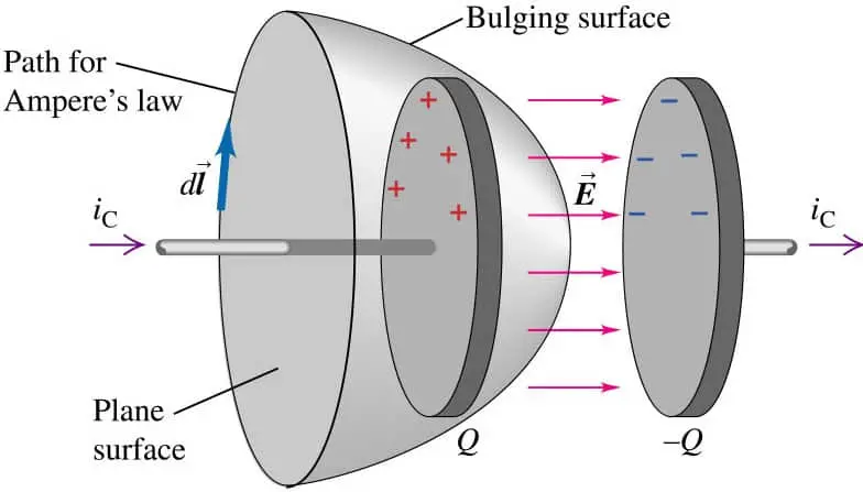 closed curve $C$ to the current passes through the surface bounded by that curve. In this statement there is a flaw! As shown in the figure, there are two surfaces that bounded by the curve. From the plane surface passes current $i_C$ but no current exist for Bulging surface! In other words, there is only an electric flux passes through the Bulging surface. Maxwell recognized this flaw and corrected it as follow in the Ampere's law
\[\oint_C{B.dl}={\mu }_0\left(I+I_d\right)={\mu }_0I+{\mu }_0{\epsilon }_0\frac{d{\mathrm{\Phi }}_E}{dt}\]
Where $I_d$ called \textbf{Maxwell's displacement current}. This is the generalized form of Ampere's law.
Thus by definition the induced displacement current is
\[I_d={\epsilon }_0\frac{d{\mathrm{\Phi }}_E}{dt}={\epsilon }_0\frac{d}{dt}\left(\vec{E}.\vec{A}\right)\]
\[={\epsilon }_0A\,{\mathrm{cos} \theta \ }\frac{dE}{dt}=\left(8.85\times {10}^{-12}\frac{\mathrm{F}}{\mathrm{m}}\right)\left(1\ {\mathrm{m}}^{\mathrm{2}}\right)\left(\mathrm{6\times }{\mathrm{10}}^{\mathrm{6}}\frac{\mathrm{V}}{\mathrm{m.s}}\right){\mathrm{cos} 60{}^\circ \ }=26.55\ \mu\mathrm{A}\]
Note: the product of Farad($F$) and Voltage ($V$) is, by definition of capacitance $Q=CV$, the unit of charge Coulomb ($C$), on the other hand, the charge over time is defined as current which its SI unit is Ampere ($A$).
An electron and a proton are both initially moving with the same speed and in the same direction at $90{}^\circ$ to the same uniform magnetic field. They experience magnetic forces, which are initially:
(a) identical
(b) equal in magnitude but opposite in direction
(c) in the same direction and differing in magnitude by a factor of $1840$
(d) in opposite directions and differing in magnitude by a factor of $1840$
(e) equal in magnitude but perpendicular to each other.
The magnitude of magnetic force that a charged particle $q$ moving with velocity $\vec{v}$ experiences in a uniform magnetic field $\vec{B}$ is $\left|\vec{F}\right|=qvB{\,\sin \theta \ }$, where $\theta $ is the angle between the velocity and magnetic field. Here $\theta =90{}^\circ $ and $v_e=v_p$ so their magnitudes are the same. The only difference can be arising due to being positive or negative of charges.
The correct answer is B.
An electron is travelling in the positive $x$ direction. A uniform electric field $\vec{E}$ is in the negative $y$ direction. If a uniform magnetic field with the appropriate 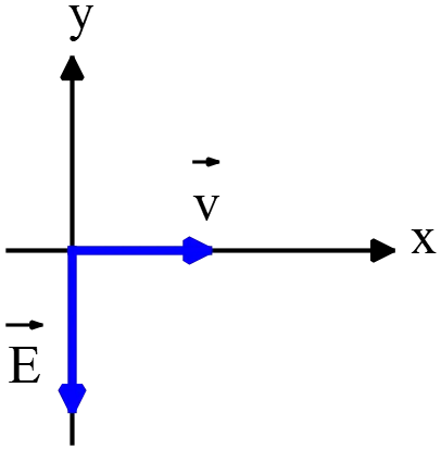 magnitude and direction also exists in the region, the total force on the electron will be zero. The appropriate direction for the magnetic field is:
(a) the positive $y$ direction
(b) the negative $y$ direction
(c) into the page
(d) out of the page
(e) the negative $x$ direction
because of vanishing net force on the electron so the magnitude of forces must be equal i.e. $F_E=F_B$ and oriented in opposite directions. We know that the direction of the forces applied on a charged moving particle is determined by right hand rule. Point your fingers of right hand along the velocity of particle so that the palm facing the direction of the magnetic field. Curl them toward $\vec{B}$. Your extended thumb points in the direction of force $\vec{F}$.
The electric field is in the $-y$ direction so the magnetic field must be in $+y$ direction. Using right hand rule, $\vec{B}$ points in the page.
The correct answer is C.
The diagrams show five possible orientations of a magnetic dipole $\vec{\mu }$ in a uniform magnetic field $\vec{B}$ . For which of these does the magnetic torque on the dipole have the greatest magnitude?
(a) I
(b) II
(c) III
(d) IV
(e) V
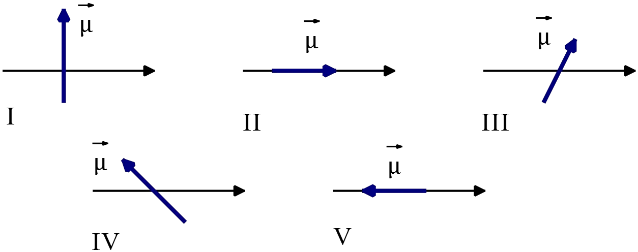
The magnetic torque on a dipole is defined as $\vec{\tau }=\vec{\mu }\times \vec{B}$ or its magnitude is
\[\left|\vec{\tau }\right|=\mu B{\,\sin \theta \ }\]
Where $\theta $ is the angle between dipole and magnetic field.
In (I), $\theta =90{}^\circ \Rightarrow \left|\vec{\tau }\right|=\mu B$
In (II), $\theta =0{}^\circ \Rightarrow \ \left|\vec{\tau }\right|=0$
In (V), $\theta =180{}^\circ \Rightarrow \ \left|\vec{\tau }\right|=-\mu B$
In (III) and (IV) the angles are between the states of (I) and (V) that is $0{}^\circ <\theta <180{}^\circ $ so their magnitude must be where between (I) and (V). therefore, the configuration (I) has the greatest magnitude of torque.
The correct answer is A.
Two parallel wires, $\mathrm{4\ cm}$ apart, carry currents of $\mathrm{2\ A}$ and $\mathrm{4\ A}$ respectively, in opposite directions. The force per unit length of one wire on the other is:
(a) $1\times {10}^{-3}\mathrm{N/m}$, repulsive
(b) $1\times {10}^{-3}\mathrm{N/m}$, attractive
(c) $4\times {10}^{-5}\mathrm{N/m}$, repulsive
(d) $4\times {10}^{-5}\mathrm{N/m}$, attractive
(e) None of these.
A wire of length $l$ carrying current $I$ can experience a force on itself due to the presence of an external magnetic field. This force, which can be used to define the SI unit amperes, is found by $\vec{F}=i\vec{l}\times \vec{B}$ or its magnitude is $\left|\vec{F}\right|=ilB{\,\sin \theta \ }$, where $\theta $ is the angle between the direction of the current in the wire and magnetic field.
When there is two wires, one of them acts as a source of external magnetic field for the second wire. Recall that the magnetic field of a straight current carrying wire by amperes law is found as
\[B={\mu }_0\frac{I}{2\pi r}\]
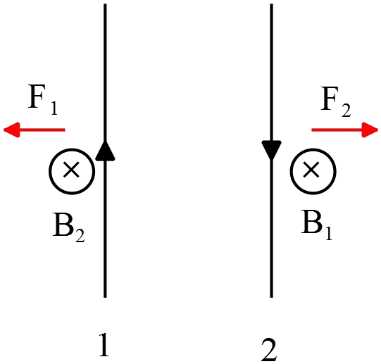
Therefore, as shown in the figure, the magnetic force on wire $2$ due to the magnetic field of wire $1$ at the location of wire $1$ is calculated as follows
\[F_2=i_2l_2B_1=i_2l_2\left(\frac{{\mu }_0i_1}{2\pi d}\right)\]
Where $d$ is the distance between the wires. So the force per unit length of wire 2 is
\[\frac{F_2}{l_2}={\mu }_0\frac{i_1i_2}{2\pi d}=\left(4\pi \times {10}^{-7}\right)\frac{2\times 4}{2\pi (4\times {10}^{-2})}=4\times {10}^{-5}\frac{\mathrm{N}}{\mathrm{m}}\]
To find the direction of the force use the right hand rule. Point your fingers of right hand along the direction of the current in the wire with the palm facing $\vec{B}$ and wrap your fingers toward the $\vec{B}$. The direction of the upright thumb is the direction of the magnetic force. As shown in the figure, the forces are in the opposite direction so are repulsive.
The correct answer is C.
Magnetic field lines inside the solenoid shown are: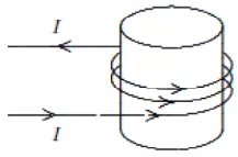
(a) clockwise circles as one looks down the axis from the top of the page
(b) counterclockwise circles as one looks down the axis from the top of the page
(c) toward the top of the page
(d) toward the bottom of the page
(e) in no direction since $\mathrm{B\ =\ }0$
The direction of a current-carrying wire is found by the right hand rule as point the thumb of your right hand along the direction of the current. Curling the four fingers shows the direction of the magnetic field. In this case four fingers curls toward the top of the page into the solenoid.
The correct answer is C.
A square loop of wire lies in the plane of the page. A decreasing magnetic field is directed into the page. The induced current in the loop
(a) counterclockwise
(b) clockwise
(b) zero
(c) up the left edge and from right to left along the top edge
(d) through the middle of the page
Lenz's law says that the induced current in a loop must be in direction that the associated magnetic field produced opposes the change in the magnetic flux through the area enclosed by the loop.
A decreasing magnetic field has a decreasing flux through the loop. A clockwise current in the loop create a magnetic field into the page so that the corresponding flux compensate the decreasing original flux through the loop.
The correct answer is B.
A cylindrical region of radius $\mathrm{R\ =\ 3.0\ cm}$ contains a uniform magnetic field parallel to its axis. If the electric field induced at a point $\mathrm{R/2}$ from the cylinder axis is $\mathrm{4.5\times }{\mathrm{10}}^{\mathrm{-}\mathrm{3}}\mathrm{\ V/m}$ the magnitude of the magnetic field must be changing at the rate of:
(a) $0\ \mathrm{T/s}$
(b) $0.30\ \mathrm{T/s}$
(c) $0.60\ \mathrm{T/s}$
(d) $1.2\ \mathrm{T/s}$
(e) $2.4\ \mathrm{T/s}$
Faraday's law tells us that a changing magnetic field with time induces an emf and a current in the loop that is $\mathcal{E}=-d{\rm{\Phi}}_B/dt$, where the minus sign is an indication of Lenz's law.
This induced current implies the presence of an induced electric field $\vec{E}$ that is tangent to the loop. Recall that the line integral of $\vec{E}\cdot d\vec{s}$ over a specific path defines the potential electric.
In this case, there is a closed loop and an induced electric field so the line integral of the above quantity gives the induced emf in the loop i.e. $\mathcal{E}=\oint{\vec{E}\cdot d\vec{s}}$.
By equating these relations, we get an alternative and useful form of Faraday's law as \[\oint{\vec{E}\cdot d\vec{s}}=-\frac{d{\mathrm{\Phi }}_B}{dt}\] Therefore, it is sufficient to evaluate both sides of above relation at the location of $R/2$.
\begin{align*} -\frac{d{\rm{\Phi}}_B}{dt}&=\oint{\vec{E}\cdot d\vec{s}}\\\\ -\frac{d}{dt}\left(BA\right)&=E\oint{ds}\\\\ -\frac{dB}{dt}(\pi r^2)&=E\left(2\pi r\right) \\\\ \Rightarrow \left|\frac{dB}{dt}\right|&=\frac{2E}{r}=\frac{2E}{\frac{R}{2}}\\\\&=4\frac{\left(4.5\times {10}^{-3}\right)}{3\times {10}^{-2}}=0.6\quad {\rm \frac Tm}\end{align*}
In the second equality, we have used the formula of magnetic flux. In the third equality since the area of the cylinder of radius, $R/2$ is constant so it is factored out of the derivative.
The correct answer is C.
A sinusoidal electromagnetic wave with an electric field amplitude of $\mathrm{100\ V/m}$ is incident normally on a surface with an area of $1\ {\mathrm{cm}}^{\mathrm{2}}$ and is completely absorbed. The energy absorbed in $\mathrm{10\ s}$ is:
(a) $1.3\ \mathrm{mJ}$
(b) $13\ \mathrm{mJ}$
(c) $27\ \mathrm{mJ}$
(d) $130\ \mathrm{mJ}$
(e) $270\ \mathrm{mJ}$
The rate at which energy passes through a unit area by electromagnetic waves is described by a quantity called Poynting vector $\vec{S}$ which is defined as
\[\vec{S}=\frac{1}{{\mu }_0}\vec{E}\times \vec{B}\]
The magnitude of Poynting vector, by definition, represents power per unit area. Because the fields $E$ and $B$ of a sinusoidal electromagnetic wave vary with time it is great important to evaluate the time average of $S$ over one or more cycles. Hence, the average of $S$, which called intensity of the waves $I$, is
\[I=S_{ave}=\frac{E^2_{max}}{2{\mu }_0c}=\frac{cB^2_{max}}{2{\mu }_0}\]
Here the average of Poynting vector is
\[S_{ave}=\frac{{\left(100\right)}^2}{2\left(4\pi \times {10}^{-7}\right)\left(3\times {10}^8\right)}=13.2\ \mathrm{W}\]
As mentioned, $S_{ave}=P_{ave}/A$ and $P_{ave}=E_{ave}/t$ where $P_{ave}$ is the power of the source and $E_{ave}$ is the corresponding energy . therefore
\[S_{ave}=\frac{E_{ave}}{At}\]
\[\Rightarrow E_{ave}=\left(13.2\mathrm{\ W}\right)\left(1\times {10}^{-4}{\mathrm{m}}^{\mathrm{2}}\right)\left(10s\right)=13.2\times {10}^{-3}\mathrm{J=13.2\ mJ}\]
The correct answer is B.
© 2015 All rights reserved. by Physexams.com
AP® is a trademark registered by the College Board, which is not affiliated with, and does not endorse, this website.