- Home
- Physics Problems
- Problems
Solved Problems
In the figure a magnetic field $\vec{B}=3t^2\left(-\hat{k}\right)$ is perpendicular to the rectangular loop of sides $1 \,{\rm m}$ and $2\, {\rm m}$ and total resistance $R=3\,\Omega $
(a) Find the magnetic flux through the loop
(b) Find the magnitude of the induced current at $t=2\ {\rm sec}$.
(c) Show the direction of the induced current on the figure.
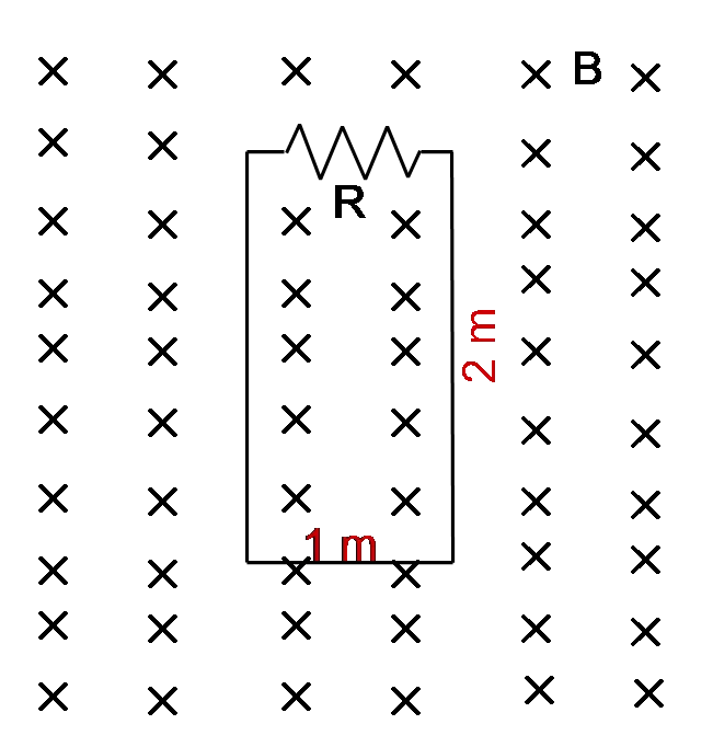
(a) The magnetic flux through any loop is defined as ${\Phi }_M=\vec{B}\cdot\vec{A}$, so \[\Phi_M=3t^2(-\hat{k})\cdot 2(-\hat{k})=6t^2\]
(b) Faraday's law states that the induced emf in any closed loop (circuit) is the negative of the time rate of change of the magnetic flux through it i.e. \[\mathcal E=-\frac{d \Phi_M}{d t}=-12t\]
So the magnitude of induce current in the loop is $I_{ind}=|\mathcal E|/R$ so \[I_{ind}=\frac{12t}{3}=4{\left.t\right|}_{t=2{\rm s}}=8\ {\rm A}\] Since the magnetic field $B$ is increasing, the magnetic flux through the loop is also increasing.
Lenz's law tells us that the direction of the induced current is such that the induced magnetic field opposes the original flux change.
Thus, the induced current must be counter-clockwise.
(c) see part (b)
A circular loop of wire has a $15\,\Omega $ resistance and a radius of $40.0\ {\rm cm}$. There is initially an external magnetic field of $3.0\ $Tesla going down through the loop into the page. At $t=0$, the external magnetic field begins to change in such a way that after $8\ {\rm s}$ it has a magnitude of $1\ {\rm T}$ and is pointing up through the loop out of the page). During the interval $t=0$ through $t=8\ {\rm s}$,
(a) Calculate the magnitude of the average induced current through the loop, and
(b) Determine the direction of the average induced current through the loop.
(c) Briefly explain why I had to add the word ``average'' in (a) and (b) above.
(a) From the Ohm's law the current through a metal wire is $I=({\rm potential\ drop)/R}$ so first using the Faraday's law find the emf induced in this loop and then substitute it in the Ohm's law. By definition, the emf is
\[{\mathcal E}=-\frac{\Delta \Phi_M}{\Delta t}\ ,\ {\rm where}\ \Phi_M=BA\]
Since there is an increasing magnetic field, the change of the flux is
\[\Phi_8=B_8A=B_8\pi r^2=(1)\pi{\left(0.40\right)}^2=0.5024\ {\rm out\ \ \ or\ -0.5024\ }\left({\rm T.}{{\rm m}}^{{\rm 2}}\right){\rm \ \ in}\]
\[\Phi_0=B_0A=3\pi{\left(0.40\right)}^2=1.5072\ {\rm into}\]
\[\Delta \Phi_M=\Phi_8-\Phi_0=\left(-0.5024\ {\rm in}\right){\rm -}\left(1.5072\ {\rm in}\right){\rm =-2.01\ }\left({\rm T.}{{\rm m}}^{{\rm 2}}\right)\ \ {\rm into}\]
In above, we have assigned a convention that into (out of) the page to be negative(positive).
The flux is decreasing, so by Lenz's law, the induced current must be in a direction to produces an induced field to oppose with this decreasing that is it must be clockwise!
\[{\mathcal E}=-\frac{\Delta \Phi_M}{\Delta t}=-\frac{-2.01}{8-0}=0.2512\ {\rm V}\]
\[{\rm Oh}{{\rm m}}^{{\rm '}}{\rm s\ law}\ :\ I_{induced}=\frac{{{\mathcal E}}_{av}}{R}=\frac{0.2512}{15}=0.01675\ {\rm A}\]
(b) Stated above. (clock wise)
(c) Since we don’t know the magnitude of the flux through the loop for all time, so we must use the word average.
A tightly wrapped circular coil of radius $r=0.18\ {\rm m}$ with $100$ turns (wraps) of wire, is sitting on a table. The ends of the wire are attached to a small light bulb whose filament has a resistance of $R=375\ \Omega $. A magnetic field $\vec{B}$, which the entire coil feels, is then turned on. The field makes an angle of $37{}^\circ $ with respect to the normal to the coil and its magnitude changes according to the following graph.
(a) What is the flux $\Phi $ of the magnetic field through a single wrap of the coil at the instant $t=0.100\ {\rm s}$?
(b) What is the time rate of change of the flux through the entire coil from $t=0s$ to $0.1s$?
(c) What is the induced emf during the period from $t=0\, {\rm s}$ to $t=0.1\ {\rm s}$?
(d) What induced current flows through the filament of the light bulb during the interval from $t=0\, {\rm s}\ $to $t=0.1\,{\rm s}$?
(e) Looking at the coil above the table, is the current flow through the coil clockwise or counter-clockwise?
(f) From the time $t=0.1\,{\rm s}$ to $t=0.150\, {\rm s}$, what induced emf is developed across the ends of the filament?

(a) ${\Phi }_M=\vec{B}.\vec{A}=BA\,{\cos 37{}^\circ \ }=10\times \pi{\left(0.18\right)}^2\times \left(0.8\right)=0.813\ {\rm Wb}$
(b)
\[\frac{\Delta {\Phi }_M}{\Delta t}=\frac{{\Phi }_M\left(t=0.1\right)-{\Phi }_M\left(t=0\right)}{0.1-0}=\frac{100\times 0.813-0}{0.1}=813\ {\rm Wb/s}\]
Note: the total flux through the entire coil is ${\Phi }_{tot}=N\Phi $
(c) ${\mathcal E}=-\frac{\Delta {\Phi }_M}{\Delta t}\to \ \left|{\mathcal E}\right|=813{\rm V}$
(d) $I_{ind}=\frac{{\mathcal E}}{R}=\frac{813}{375}=2.16{\rm A}$
(e) By Lenz's law, due to the increasing flux through the coil, the induced magnetic field produced by this current should be in direction to oppose the external magnetic field so using right hand rule the induced current is clockwise.
(f) Because the area of the coil is constant and during the time $\left[0,0.15{\rm s}\right]$ the variation of the magnetic field is zero so $\Delta {\Phi }_M=0\Rightarrow {\mathcal E}=0$
A rectangular loop with width $L$ and a slide wire with mass $m$ is as shown in the figure.
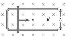
A uniform magnetic field $\vec{B}$ is directed perpendicular to the plane of the loop into the plane of the figure. The slide wire is given an initial speed of $v_0$ and then released. There is no friction between the slide wire and the loop, and the resistance of the loop is negligible in comparison to the resistance $R$ of the slide wire.
(a) Obtain an expression for $F$, the magnitude of the force exerted on the wire while it is moving at speed $v$
(b) Show that the distance $x$ that the wire move before coming to rest is $x=mv_0R/a^2B^2$
(a) Due to the change of flux (as the slide moves the area of the loop varies), there is an induced current in the slide wire. By definition,
\begin{align*} \mathcal E&=-\frac{d}{dt}\Phi_B \\\\ &=-\frac{d}{dt}\left(\vec{B}\cdot \hat{n}dA\right) \\\\ &=-B\frac{dA}{dt} \quad \text{where} A=Lx \end{align*} In the above $\hat{n}$ is a unit vector perpendicular to the area of the surface, which in this case, makes an angle of $90^\circ$ with the surface of the loop. By definition of scalar product, we have $\vec{B}\cdot \hat{n}=B\cos\theta=B\cos 0=B$. Hence, the induced emf in the loop is found to be \[\mathcal E=-BL\frac{dx}{dt}=-BLv\]
From Ohm's law formula, we can obtain the induced current in the slide wire as below: \[i_{ind}=\frac{\mathcal E}{R_{wire}}=\frac{BLv}{R}\]
In the above, the minus sign has been omitted since this negative is a sign of Lenz's law!
When the wire moves to the right, the flux through the loop is increasing, so by Lenz's law; the direction of induced current must be counterclockwise that is the current in the wire must be upward, say in the positive $y$ direction (or $\hat{j}$).
On the other hand, we are in a situation where there is a current-carrying wire in a uniform magnetic field. In these cases, the magnetic force on the wire is determined by the formula $\vec{F}=i\vec{L}\times \vec{B}$ where $\vec{L}$ is a vector that its magnitude determines the straight length of the wire is in the magnetic field, and its direction shows the direction of the current in the wire. \begin{align*}\vec{F}&=i\vec{L}\times \vec{B} \\ &=i(L\hat{j}) \times B(-\hat{j}) \\ &= iLB\,(\hat{j}\times (-\hat{k})) \\ &=-iLB\hat{i}\end{align*} Substituting the induced current found in above into this expression, we will have \[\vec{F}=\frac{B^2L^2v}{R}(-\hat{i})\] $-\hat{i}$ indicates the direction of the magnetic force on this wire that is to the left.
(b) Use Newton's second law and definition of the instantaneous acceleration and some manipulation to find instantaneous velocity of the wire as follows:
\begin{gather*}\vec{F}=m\vec{a}=m\frac{dv}{dt}\\ \\-\frac{B^2L^2v}{R}=m\frac{dv}{dt}\\ \\\to -\frac{B^2L^2}{Rm}dt=\frac{dv}{v}\end{gather*} By integrating both sides, we have \begin{gather*} \int^v_{v_0}{\frac{dv}{v}}=-\int{\frac{B^2L^2}{mR}dt}\\ \\ \to \quad {\ln \frac{v}{v_0}\ }=-\frac{B^2L^2}{mR}t \\ \\ \Longrightarrow \quad v=v_0\,{\exp \left(-\frac{B^2L^2}{mR}t\right)}\end{gather*}
We can check its correctness by substituting the initial and final time into it:
$t=0\to v=v_0\ $and $t\to \infty \ \Longrightarrow v=v_0\,e^{-\infty }\to 0$
Now use the definition of the instantaneous velocity to determine the desired distance $x$ as below \begin{align*} v&=\frac{dx}{dt} \\ \\ \to x &= \int{v\left(t\right)dt}\\ \\&=v_0\int{{\exp \left(-\frac{B^2L^2}{mR}t\right)}dt}\\\\ &=-\frac{mRv_0}{B^2L^2}{\left.{\exp \left(-\frac{B^2L^2}{mR}t\right)\ }\right|}^t_0\\ \\&=\frac{mRv_0}{B^{2}L^2}\left(1-e^{-\frac{B^{2}L^2}{mR}t}\right)\end{align*}
In the limit that $t$ becomes infinitesimally small $t\to \infty$ we get $x(t)=\frac{mR}{B^{2}L^{2}}v_0$.
A circular loop of wire is in a region of spatially uniform magnetic field, as shown in the figure below. The magnetic field is directed into the plane of the figure. 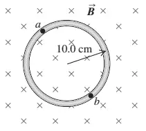 Determine the direction (clockwise or counterclockwise) of the induced current in the loop when
(a) B is increasing;
(b) B is decreasing;
(c) B is constant with value $B_0$ Explain your reasoning.
Lenz's law determines the direction of the induced current. This law states that the direction of the induced current must be such that the produced magnetic field by this current opposes the original flux change.
(a) Since the area of the loop is constant and $\frac{dB}{dt}>0$, so by the definition of the magnetic flux i.e. ${\Phi }_M=\vec{B}.\hat{n}\ dA$, there is an increasing magnetic flux. By Lenz's law, the induced magnetic field must be opposite to the original field (downward), thus the induced current must be counterclockwise to produce an upward magnetic field.
(b) With the similar reasoning as above, by Lenz's law the induced current must be in a direction to cancel out the decreasing downward flux so the current is clockwise.
(c) If $\frac{dB}{dt}=0$ then from $\frac{d}{dt}\Phi =\frac{d}{dt}\vec{B}.\hat{n}dA$, there is no change in flux and thus there is no induced current.
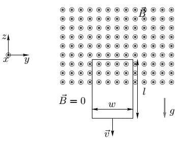
A rectangular loop of wire with mass m, width w, vertical length l, and resistance R falls out of a magnetic field under the influence of gravity. The magnetic field is uniform and out of the paper ($\vec{B}=B\hat{x}$) within the area shown (see sketch) and zero outside of that area. At the time shown in the sketch, the loop is exiting the magnetic field at speed $\vec{V}\left(t\right)=V\left(t\right)\hat{z}$ , where ($V\left(t\right)<0$ meaning the loop is moving downward, not upward). Suppose at time $t$ the distance from the top of the loop to the point where the magnetic field goes to zero is $z(t)$ (see sketch).
(a) What is the relationship between $V(t)$ and $z(t)$? Be careful of your signs here, remember that $z(t)$ is positive and decreasing with time, so $dz(t)/dt<\ 0$.
(b) If we define the area vector $\vec{A}$ to be out of the page, what is the magnetic flux $f_B$ through our circuit at time $t$ (in terms of $z(t)$, not $V(t)$).
(c) What is $d\Phi_B/dt$ ? Is this positive or negative at time $t$? Be careful here, your answer should include $V(t)$(not $z(t)$and remember that $(t)<\ 0$ ).
(d) What is the direction (clockwise or counterclockwise) and magnitude of the induced current on the loop of wire?
(e) What is the direction (into the page or out of the page) of the self-magnetic field due to the induced current inside the circuit loop?
(f) Besides gravity, what other force acts on the loop in the $\pm \ z$-direction? Give the magnitude and direction of this force in terms of the quantities given. (Hint: use $d\vec{F}=Id\vec{L}\times \vec{B}$)
(g) What is the magnitude of the terminal velocity?
(a) Use the definition of the instantaneous velocity that is $v=dz/dt$. Since
\begin{gather*}\vec{V}(t)=V(t)\hat{z} \\\\ \text{where} \quad V(t)<0 \quad \text{and} \quad z(t)>0 \\ \\ \text{then} \quad \frac{d}{dt}z(t)=V(t)<0 \end{gather*}
(b) \begin{align*} \Phi_B&=\int{\vec{B}\cdot \hat{n}\, dA} \\\\ &=\int{BdA\,\cos 0} \\\\ &=B\int{da}=B(rectangular\ loop\ area) \\\\ &=Bwz(t)>0 \end{align*}
(c) Applying magnetic flux formula, we have \begin{align*}\frac{d\Phi_B}{dt}&=\frac{d}{dt}\left(Bwz\left(t\right)\right)\\\\&=wB\frac{d}{dt}z\left(t\right)\\\\&=BwV\left(t\right)<0\end{align*}
(d) Using Faraday's law of induction, we have \[{\mathcal E}=-\frac{d\Phi_B}{dt}=-BwV\left(t\right)>0\] Therefore, using Ohm's law, we get \[I=\frac{\left|{\mathcal E}\right|}{R}=\frac{wB\left|V\left(t\right)\right|}{R}\]
Due to Lenz's law, the induced current must be counterclockwise so that the magnetic field produced by this current opposes the decreasing flux.
(e) As noted above, by using the right-hand rule $B'$ is out of the page.
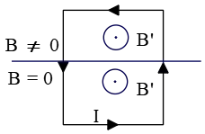
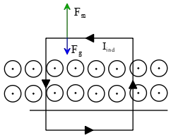
(f) Since there is an induced current in the loop and lies in an external magnetic field so a magnetic force ${\vec{F}}_m=I_{ind}\vec{L}\times {\vec{B}}_{ext}$ exerts on it in the up direction. Thus, its magnitude is
\[L\bot B\Rightarrow \ \ F_m=I_{ind}wB_{ext}\]
see figure below.
(g) When net force on the object is zero, the object has zero acceleration, in the other words, this object is moving at its terminal velocity. In this problem, two forces, gravity and magnetic, act on the upper side of the loop. So the magnetic force acts as the drag force! Write out this conditions, we obtain
\[\Sigma F_y=ma_z=0\Rightarrow F_m\hat{j}+mg\left(-\hat{j}\right)=0\]
$F_m=F_g\to \ \ I_{ind}wB_{ext}=mg\ $where the induced current is found in part(d)
\[I_{induced}=\frac{wB_{ext}v_{terminal}}{R}\]
\[\Longrightarrow w^2B^2\frac{v_{ter}}{R}=mg\ \ \Rightarrow \ \ v_{ter}=\frac{Rmg}{w^2B^2}\]
Determine the magnitude of the mutual inductance between an infinite straight wire and a circular loop of radius $R$, that has its center a distance $d$ from the axis of the straight wire ($d>R$)
Hint: $\int^{2\pi}_0{\frac{d\theta}{a+b{\cos \theta\ }}}=\frac{2\pi}{\sqrt{a^2-b^2}}$

Apply a current $I_1$ in the straight wire and find the flux passing through the loop.
From Ampere's law $\oint{\vec B.d\vec \ell}=\mu_0I\ $ the magnetic field produced by straight wire at distance $r$ is $B_1=\frac{\mu_0I_1}{2\pi r}$.
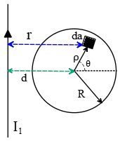
Using the definition of flux passing through the loop, we have
\[{\Phi }_{21}=\int {\vec{B}}_1.\hat{n}\ da=\frac{\mu_0I_1}{2\pi}\int^R_0{\rho d\rho}\int^{2\pi}_0{\frac{d\theta}{r}}\]
Where $r=d+\rho\,{\cos \theta\ }$ and $da=\rho d\rho \,d\theta$ is the area element in polar coordinates.(see figure). ${\Phi }_{21}$ is the flux produced by the current $I_1$ and passed the loop.
Using the hint $\int^{2\pi}_0{\frac{d\theta}{d+\rho\,{\cos \theta\ }}=2\pi/\sqrt{d^2-\rho^2}}$ ,one can show that \[{\Phi }_{21}=\mu_0I_1\ \int^R_0{\frac{\rho d\rho}{\sqrt{d^2-\rho^2}}}\\] For determining the integral above we use the change of variables
let $u\equiv d^2-\rho^2$ , $\rho d\rho=-\frac{du}{2}$ \begin{align*}{\Phi }_{21}&=\mu_0I_1\ \int^R_0{\frac{\rho d\rho}{\sqrt{d^2-\rho^2}}}\\ \\&=-\frac{1}{2}\mu_0I_1 \int^{d^{2}-R^{2}}_{d^{2}}{\frac{du}{\sqrt{u}}}\\ \\&=\mu_0I_1 \left(d-\sqrt{d^2-R^2}\right)\end{align*} Thus, the mutual inductance, by definition, is
\[M_{21}=\frac{{\Phi }_{21}}{I_1}=\mu_0\left(d-\sqrt{d^2-R^2}\right)\]
A slide wire generator is shown in the figure where there is a perpendicular constant magnetic field $B$, uniform everywhere. Assume that the total 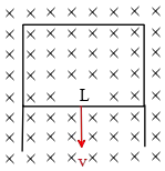 resistance of the rectangular loop to be only due to the sliding part given by $R$. Now, if the sliding rod (length $L$) is pulled at a constant velocity $v$ shown in the figure, find:
(a) The rate at which energy is dissipated around this loop.
(b) The rate at which mechanical work is done to move the rod through the magnetic field. The dimensions of the stationary parts of the loop are not specified.
(a) The power supplied or dissipated in an electric circuit is $P=RI^2={\mathcal E}I=\frac{{{\mathcal E}}^2}{R}$. Therefore, we must first find the emf of the circuit and then substituting it into one of the above relations. Since we have a changing flux, so an emf produce in the loop. By definition its magnitude is
\begin{align*}{\mathcal E}&=-\frac{d{\Phi }_B}{dt}\\&=-B\frac{dA}{dt}\\\&=-BL\frac{d}{dt}\left(vt\right)\\&=-BvL\\ \\ P_{diss}&=\frac{{{\mathcal E}}^2}{R}=\frac{B^2v^2L^2}{R}\end{align*}
(b) As soon as the current $I$ starts flowing around the loop, a magnetic force $F$ exerts on the wire that is found by $F=ILB=\frac{BvL}{R}.LB=B^2L^2v/R$. Now by definition, the mechanical power is \[P_{mech}=\frac{work}{time}=\frac{dW}{dt}=\frac{d}{dt}\left(\vec{F}.\vec{x}\right)=\vec{F}.\frac{d\vec{x}}{dt}=\vec{F}.\vec{v}\] Substituting the force exerted into this relation, we obtain
\[P_{mech}=Fv=\frac{B^2L^2v^2}{R}\]
Note that the $P_{diss}=P_{mech}$ a consequence of conservation of energy!
A loop of wire with N=100 turns and a radius of 3 m is situated in a  decreasing magnetic field of $1\ {\rm T/sec}$ whose direction is depicted below.
(a) What is the direction of the induced current? Draw the direction of the diagram and explain your reasoning.
(b) What is the magnitude of the current if the resistance of the loop is $10\,\Omega $?
(a) The direction of the induced current predicted by Lenz's law. 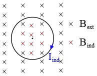 According to this law, the direction of the induced current is such that the magnetic field produced by it, opposes the change in flux of the original magnetic field. Because the original magnetic field is decreasing so a clockwise induced current compensates for the original decreasing magnetic flux passing through the loop.
(b) A change in magnetic flux passing through any closed loop produces an induced emf and current in the loop. This is Faraday's law of magnetic induction. In mathematical language is
\[{\mathcal E}=-\frac{d{\Phi }_M}{dt}=-\frac{d}{dt}(\vec{B}.\vec{A})\]
Where ${\Phi }_M$ is the magnetic flux. If the loop has $N$ turns then the total flux passing through them is $N$ times the flux through each of them.
First, use Faraday's law equation to find the induced emf created in the wire then use the Ohm's law and determine the magnitude of the induced current. \begin{gather*}{\mathcal E}=-N\frac{d\Phi }{dt}=-NA\frac{dB}{dt}=-N\left(\pi r^2\right)\frac{dB}{dt}\\ \\{\mathcal E}=-100\left(\pi \times 3^2\right)(\underbrace{-1}_{decreasing})=+900\pi \ {\rm V}\end{gather*}
Then, using Ohm's law gives \[I_{ind}=\frac{{\mathcal E}}{R}=\frac{900\pi}{10}=90\pi\ {\rm A}\]
What is the emf induced in a solenoid with an inductance of 0.25 H if the current is uniformly reduced from 2.0 A to 0 A in 1/16 of a second?
We have two inductances, one is the mutual inductance which is present in two separate and independent circuits, and the other is self-inductance that occurs only in a single isolated circuit.
When a current is present in a circuit, it creates a magnetic field that causes a magnetic flux through that circuit. This flux changes when the current changes. Recall that Faraday's law states that the change in flux gives rise to an induced emf. Thus any circuit that carries a varying current has an induced emf that is produced by the variation in its own magnetic field.
The magnetic flux of $\vec{B}$ through the circuit is proportional to $I$ that is
\[{\Phi }_m=LI\]
Where $L$ is a proportionality constant which is called self-inductance of the circuit. The SI unit of it is henry $H$.
In a varying current, the flux changes and so using Faraday's law we have
\[{\mathcal E}=-\frac{d{\Phi }_m}{dt}=-L\frac{dI}{dt}\]
In this problem, $L=0.25\ {\rm H}$, $t=\frac{1}{16}\ {\rm s}$ so the induced emf is
\begin{align*}{\mathcal E}&=-L\frac{\Delta I}{\Delta t}\\ \\&=-L\frac{I_2-I_1}{\Delta t}\\\\&=-0.25\frac{0-2}{\frac{1}{16}}\\\\&=8\quad {\rm V}\end{align*}
A conducting bar of length D rotates with angular frequency $\omega$ about a pivot $P$ at one end of the bar (see the figure at right). The other 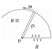 end of the bar is in slipping contact with a stationary conducting wire in the shape of a circle (we only show part of that circle to keep the drawing simple). Between point $P$ and the circular wire there is a resistor $R$ as shown. Thus the bar, the resistor, and the wire form a closed conducting loop. The resistance of the bar and the circular wire are negligibly small.
There is a uniform magnetic field $B$ perpendicular to the plane of the conducting wire, as shown. What is the induced current in the loop? Express your answer in terms of $D,\ \omega,\ R,\ $and $B$.
This configuration is into a uniform magnetic field, but its surface is changing. So there is a changing magnetic flux.
By Faraday's law, a changing magnetic flux produces an induced emf and induced current in the circuit.
First, find this induced emf, then use Ohm's law to determine the induced current. Faraday's law equation is \[{\mathcal E}=-\frac{d{\Phi }_M}{dt}=-\frac{d}{dt}\int{\vec{B}\cdot\hat{n}dA}\]
$B$ is uniform so we can factor it out of the integral. The remaining integral is the area of the changing shape which is easier to calculate it in the polar coordinate.
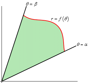
In this coordinate, the formula for finding this area is \[A=\int^\beta_\alpha{\frac{1}{2}r^2d\theta}\] Where $r$ is the distance to the center, which in this case, $r=D$ is the radius of the circle.
Therefore, the magnitude of the induced emf is \begin{align*}|{\mathcal E}|&=B\frac{d}{dt}\int{dA}\\ \\&=B\frac{d}{dt}\int^\theta_0{\frac{1}{2}D^2d\theta}\\\\&=\frac{B}{2}D^2\underbrace{\frac{d\theta}{dt}}_{\omega}\\ \\ \Rightarrow \quad {\mathcal E}&=\frac{B}{2}D^2\omega\end{align*}
Using Ohm's law, the induced current will be \[I_{ind}=\frac{{\mathcal E}}{R}=\frac{1}{2R}BD^2\omega\]
A ``rail gun projectile launcher'' is shown at right. A large current moves in a closed loop composed of fixed rails, a power supply, and a very light, almost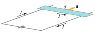 frictionless bar touching the rails. A magnetic field is perpendicular to the plane of the circuit.
(a) If the bar has a length ${\rm d=24\ cm}$, a mass of ${\rm 1.5\ g}$, and is placed in a field of ${\rm 1.8\ T}$, what constant current flow is needed to accelerate the bar from rest to a speed of ${\rm 25\ m/}{\rm s}$ in a distance of ${\rm 1.0\ m}$?
(b) In what direction must the field point?
(a) Recall that there is a force acted on a current carrying wire or bar of length $\vec{l}$ in a magnetic field $\vec{B}$ as $\vec{F}=i\vec{l}\times \vec{B}$.
Here, the bar is perpendicular to the magnetic field, so the magnitude of the force is $F=ilB$. Using Newton's second law $F=ma$, and kinematic equation $v^2-v^2_0=2a\Delta x$, we can find the current through the bar
\[ilB=m\frac{\left(v^2-v^2_0\right)}{2\Delta x}\to i=\frac{m\left(v^2-v^2_0\right)}{2lB\Delta x}\]
The bar is initially at rest, $v_0=0$ and its final velocity after travelling distance $1\ {\rm m}$ is $v=25\ {\rm m/s}$. by substituting these into above, we obtain the current
\begin{align*}i&=\frac{\left(1.5\times {10}^{-3}\ {\rm kg}\right)\left({\left({\rm 25}\right)}^{{\rm 2}}-0^2\right)}{2\left(0.24\right)\left(1.8\right)\left(1\right)}\\ \\&=1.08\ {\rm A}\end{align*}
(b) Acceleration of any object is in direction of the force $\vec{a}=\vec{F}/m$, so for the force acting on the bar to be in the direction shown in the figure, using right hand rule, the magnetic field must be into the page.
Most useful formula in Waves:
Faraday's law:
\[\mathcal E=-\frac{d\Phi_B}{dt}\]
induced electric field:
\[\oint \vec E \cdot d\vec \ell=-\frac{d\Phi_B}{dt}\]
$emf$ produced in a conductor with length $L$ moves in uniform $B$ with velocity $v$
\[\mathcal E=vBL\]
Magnetic flux through surface $A$:
\[\Phi_B=\vec B \cdot \vec A\]
Definition of self inductance:
\[L=\frac{\Phi_B}{I}\]
Self-inductance of a solenoid of length $\ell$, cross sectional area $A$ and number of turns per unit length $n$:
\[L=\mu_0 n^2 A \ell\]
Energy stored in an inductor:
\[U=\frac{1}{2}LI^2\]
© 2015 All rights reserved. by Physexams.com
AP® is a trademark registered by the College Board, which is not affiliated with, and does not endorse, this website.
